
Disk drive having airflow adjusting mechanism and thin-plate member incorporated therein

a technology of airflow adjustment and disk drive, which is applied in the direction of electrical apparatus construction details, instruments, and record information storage, etc., can solve the problems of vibration of the actuator and the storage disk, adversely affecting the head positioning accuracy and dimensional accuracy, and complicating the production process, so as to reduce the acoustic emission

Inactive Publication Date: 2006-07-04
3M INNOVATIVE PROPERTIES CO
View PDF26 Cites 20 Cited by
  • Summary
  • Abstract
  • Description
  • Claims
  • Application Information

AI Technical Summary

Benefits of technology

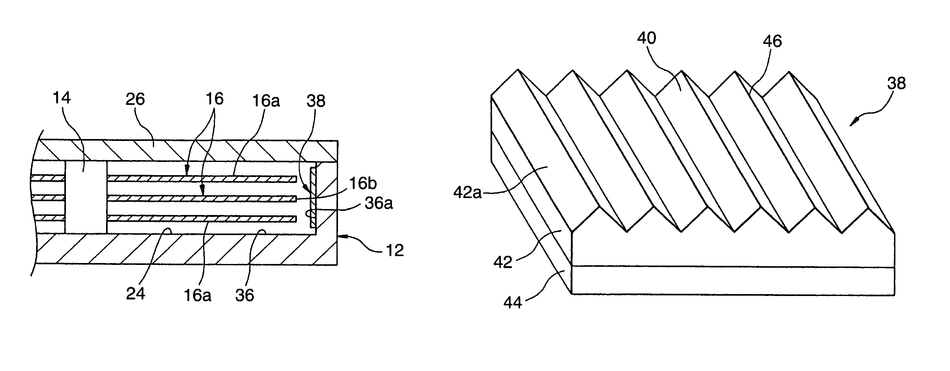
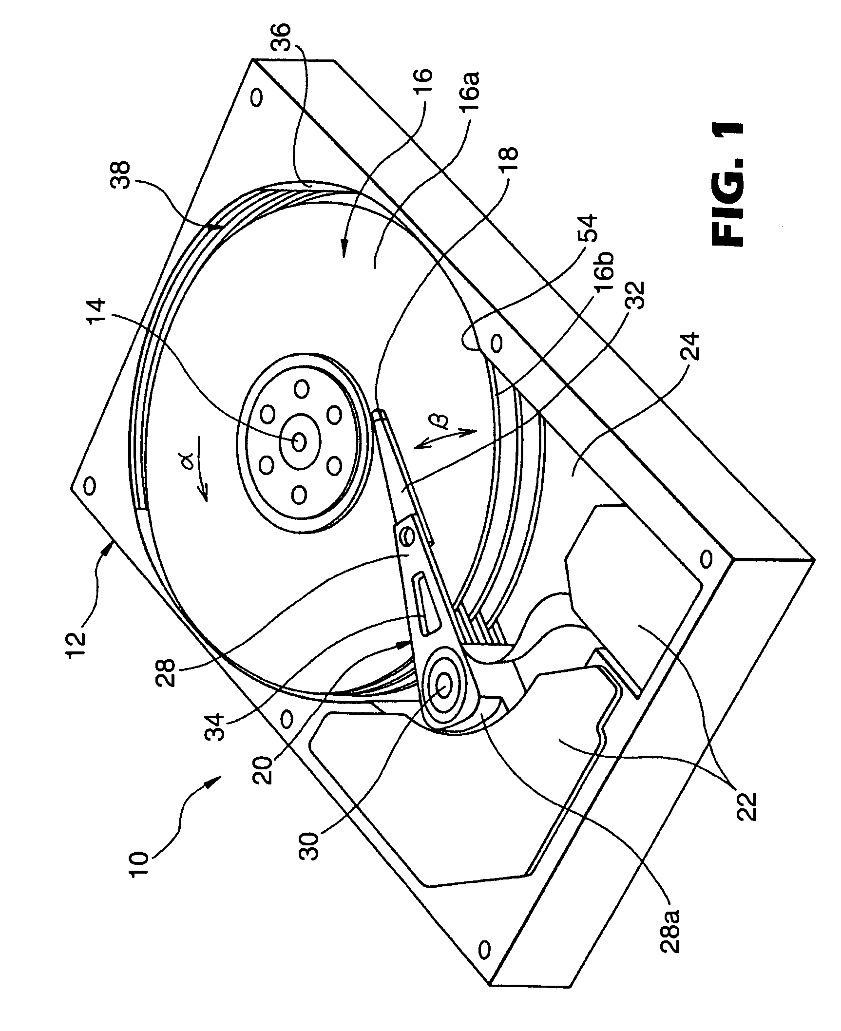
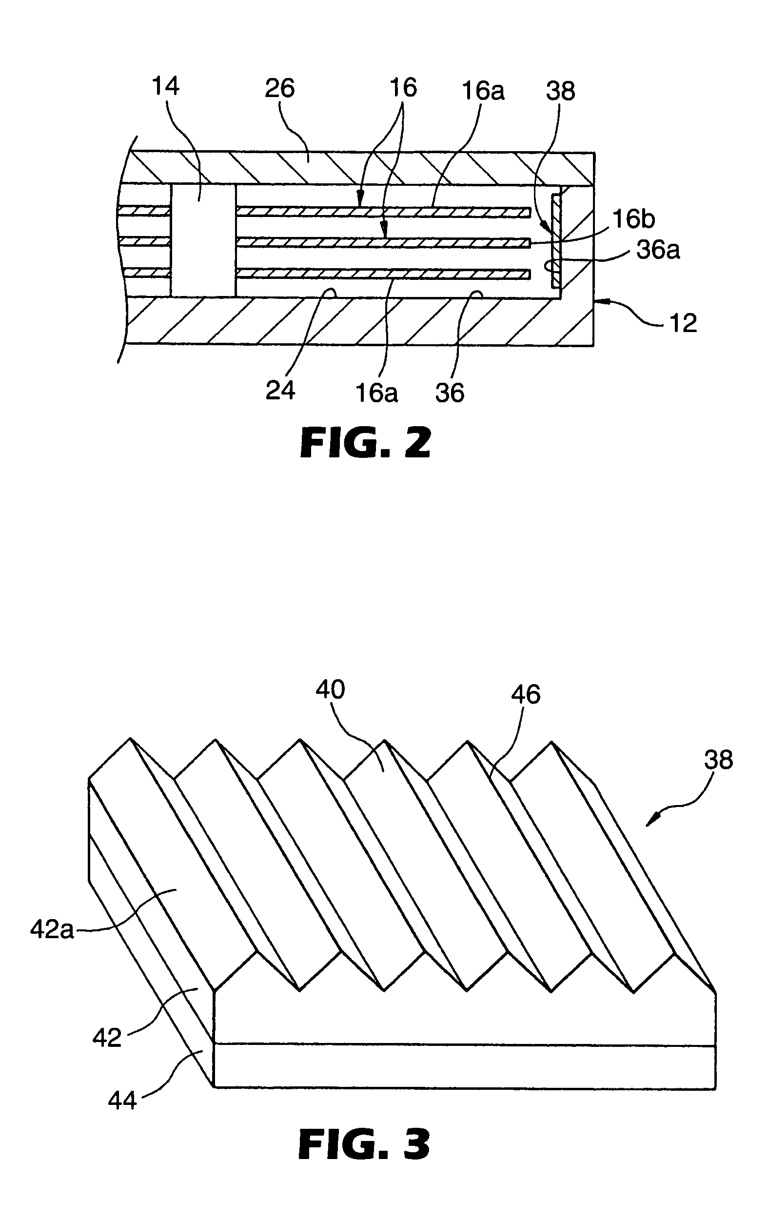
The invention provides a disk drive with an airflow adjusting mechanism for controlling the airflow around the storage disk. The mechanism includes a thin-plate member with minute protrusions that follow the shape of the inner wall surface of the casing. The thin-plate member is attached to the inner wall surface through an adhesive layer with the protrusions exposed to the recess of the casing. The thin-plate member can be positioned at various locations, such as opposed to the outer peripheral edge of the storage disk or the recording surface of the disk. The thin-plate member can also have various functions, such as reducing acoustic emissions, anti-static function, charge-surface function, absorb-moisture function, and so on.

Problems solved by technology

For example, the airflow generated around the storage disk in high-speed rotation becomes turbulent by bombarding the inner wall surface of the casing of the disk drive and may cause the vibration of the actuator and the storage disk.
The vibration of the actuator and the storage disk is a factor adversely affecting the head positioning accuracy and the dimensional accuracy of the gap between the head and the recording surface of the disk.
This machining process may complicate the production process or increase the production cost of the disk drive.

Method used


Image

  • Disk drive having airflow adjusting mechanism and thin-plate member incorporated therein
  • Disk drive having airflow adjusting mechanism and thin-plate member incorporated therein
  • Disk drive having airflow adjusting mechanism and thin-plate member incorporated therein

Examples


example

[0056]In a 8.89 cm (3.5-inch) hard disk drive having the basic configuration shown in FIG. 1, the storage disks 16 are rotated at 10000 rpm, and the vibration in a vertical direction (along the axis of the drive shaft 14) of the storage disk 16 located at the upper end was measured with a laser displacement gauge for both the structure according to this invention (FIG. 2) having the thin-plate member 38 mounted on the side surface area 36a of the inner wall surface 36 of the casing and the conventional structure lacking the thin-plate member 38. The point of measurement was set at the diametrical center of the recording surface 16a of the storage disk 16. The two types of thin-plate members 38 were used, one including the substrate layer 42 formed with the minute protrusions 40 configured of a plurality of ridges 46 (sample 1) and the other including the thin-plate member 38 having the substrate layer 42 formed with the minute protrusions 40 made up of a plurality of headed elements...


PUM

PropertyMeasurementUnit
thicknessaaaaaaaaaa
heightaaaaaaaaaa
heightaaaaaaaaaa

Abstract

A disk drive 10 includes a thin-plate member 38 fixedly attached at a desired location to an inner wall surface 36 defining a recess 24 of a casing 12. The thin-plate member 38 includes a substrate layer having a major side on which a plurality of minute protrusions are formed and an adhesive layer attached fixedly on the back side of the substrate layer. The thin-plate member 38 is fixedly attached on the inner wall surface 36 of the casing 12 through the adhesive layer with the minute protrusions being exposed to the recess 24 of the casing 12. The thin-plate member 38 has a flexibility permitting it to follow the shape of the inner wall surface 36 of the casing 12. The thin-plate member 38 reduces an interfacial friction caused between the inner wall surface 36 of the casing and the airflow generated around the storage disk 16 in rotation.

Description

[0001]This application is a 371 of PCT / US 02 / 21488 Jul. 8, 2002TECHNICAL FIELD OF THE INVENTION[0002]The present invention relates to a disk drive for writing and reading data to and from a storage disk, and particularly to a disk drive having an airflow adjusting mechanism for adjusting the airflow generated around the storage disk when rotating at high speed. The present invention further relates to a thin-plate member incorporated, as an airflow adjusting mechanism, in such a disk drive.BACKGROUND OF THE INVENTION[0003]In a disk drive used as an auxiliary storage unit of an information processing system, any one of various disk-shaped storage media (referred to as the storage disk in this specification) such as a magnetic disk, an optical disk and a magneto-optic disk is rotated at high speed, while a head section is caused to perform the tracking operation following a multiplicity of recording tracks formed concentrically on the recording surface of the recording disk thereby to...

Claims


Application Information

Patent Timeline
Patent Type & Authority Patents(United States)
IPC IPC(8): G11B33/14G11B25/04G11B33/08
CPCG11B25/043G11B33/148G11B33/08
Inventor ASANO, TOMOYUKIKAWAMOTO, IKUKO
Owner 3M INNOVATIVE PROPERTIES CO
Learn More