
Method and system for low power refresh of dynamic random access memories

a random access memory and low power refresh technology, applied in static storage, information storage, digital storage, etc., can solve the problems of limited battery life, large power consumption, and limited use of portable electronic devices such as notebook computers, and achieve the effect of reducing the refresh rate and facilitating and quick switching

Inactive Publication Date: 2006-07-04
ROUND ROCK RES LLC
View PDF64 Cites 26 Cited by
  • Summary
  • Abstract
  • Description
  • Claims
  • Application Information

AI Technical Summary

Benefits of technology

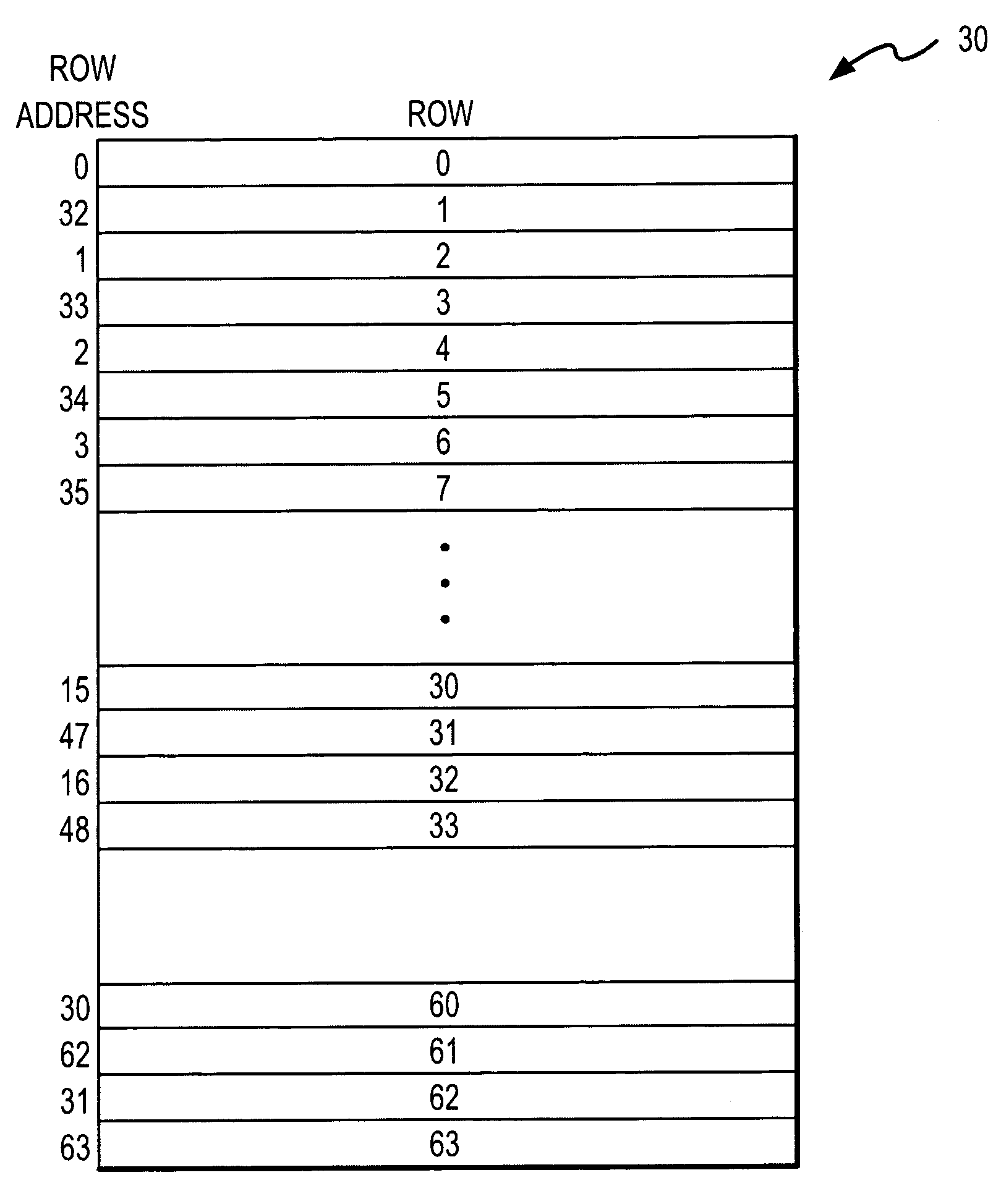
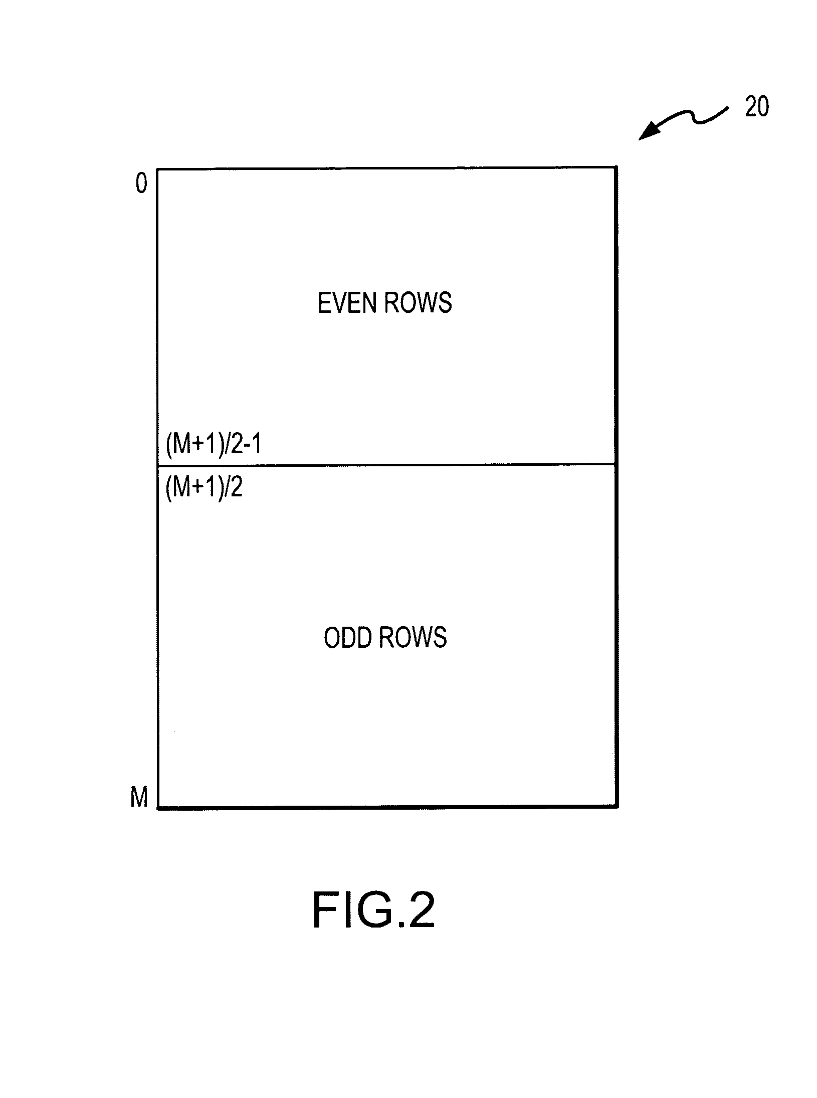
[0015]A system and method according to the invention allows a DRAM device to be easily and quickly switched back and forth between a full density mode consuming power at a relatively fast rate and a half density mode consuming power at a relatively slow rate. The row addresses applied to the DRAM device are reordered by remapping the most significant bit of each row address to the least significant bit of the row address during all operating modes. As a result, all of the odd (or even) rows of the DRAM array are populated with data before any of the even (or odd) rows are populated with data. As long as the data stored in the DRAM device uses less than half of the capacity of the DRAM device, data will then be stored only in alternate rows, and the row adjacent each row in which data are stored will be free to store data. When the DRAM device is to be switched from the full density mode to the half density mode, data stored in each row is simply transferred to the adjacent row. Thereafter when operating in the half density mode, the row corresponding to each row address and the adjacent row are accessed at the same time. Although the data stored in each row can be transferred to the adjacent row by a variety of techniques, it is preferably transferred by transferring the data from each row to the adjacent row during the first refresh of the row. More particularly, when a row is first refreshed after the DRAM device has been switched to the half density mode, the sense amplifierlifiers are left active so that the voltage levels corresponding to the data stored in the memory cells being refreshed are maintained on the respective digit line pairs. The adjacent row is then activated thereby transferring the voltage on the digit lines to the memory cells in the adjacent row. Once the data have been transferred to the adjacent rows during refresh at the full density refresh rate, the refresh rate can be significantly reduced during operation in the half density mode.

Problems solved by technology

The usefulness of portable electronic devices, such as notebook computers, is the limited by the limited length of time batteries are capable of powering the device before needing to be recharged.
For example, electronic devices, such a notebook computers, typically include dynamic random access memory (“DRAM”) devices that consume a substantial amount of power.
One operation that tends to consume power at a substantial rate is refresh of memory cells in the DRAM device.
Since refresh essentially involves reading data bits from and writing data bits to a large number of memory cells refresh tends to be a particularly power-hungry operation.
Therefore, DRAM devices are generally refreshed at a rate that is higher than the rate actually needed to prevent data from being lost, and, as a result, unnecessarily consume power.
For example, although the refresh rate may be reduced with reduced maximum operating temperature, the refresh may still result in refreshing a large number of memory cells that are not actually storing data.
Although these techniques for refreshing less than all of the memory cells in a memory device can substantially reduce the rate of power consumption, it can nevertheless require a substantial amount of power to refresh the cells that are to be refreshed.
In conventional DRAM devices, it is not possible to switch between a full density mode and a half density mode.
This limitation may be due to the difficulty in making this transition.
The difficulty of being able to rapidly switch between the full density mode and the half density mode primarily results from two requirements.
Transferring data between memory cells in this manner by conventional read / write operations would require a great deal of time and would therefore preclude quickly switching back and forth between the full density mode and the half density mode.
Also, transferring approximately half of the data stored in the DRAM device by conventional read / write operations, which would be necessary to switch from the full density mode to the half density mode, would itself consume a great deal of power.
It therefore does not seem possible to easily transition between the half density mode and the full density mode.

Method used


Image

  • Method and system for low power refresh of dynamic random access memories
  • Method and system for low power refresh of dynamic random access memories
  • Method and system for low power refresh of dynamic random access memories

Examples


Embodiment Construction

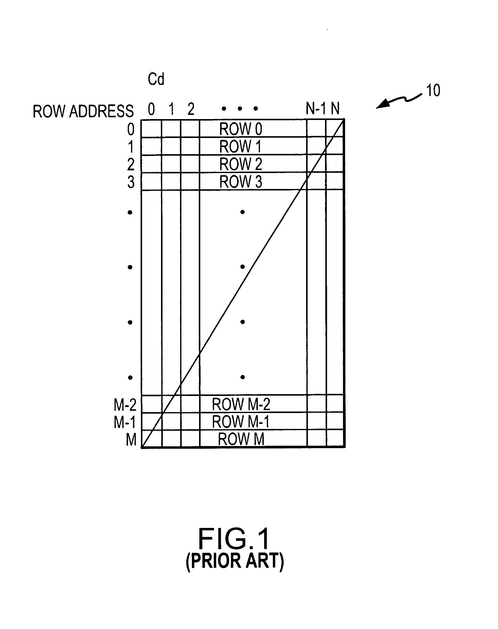
[0026]A memory map 10 for a conventional DRAM device (not shown) is shown in FIG. 1. The memory map 10 illustrates how the physical locations in an array of memory cells (not shown) in the DRAM device correspond to row and column addresses that may be applied to the DRAM device. The row and column addresses are normally binary numbers that are decoded by the DRAM to select the corresponding row or column. It is assumed for purposes of illustration that the array of memory cells that will be discussed with reference to FIG. 1 consists of M+1 rows and N+1 columns. The memory cell that is in the upper left hand corner is selected by a row address of 0 and a column address of 0. The memory cell in the upper right hand corner is selected by a row address of 0 and a column address of N. The memory cell in the lower left hand corner is selected by a row address of M and a column address of 0. The memory cell in the lower right hand corner is selected by a row address of M and a column addr...


PUM


Abstract

A method and system for operating a DRAM device in either a high power, full density mode or a low power, half density mode. In the full density mode, each data bit is stored in a single memory cell, and, in the half density mode, each data bit is stored in two memory cells that are refreshed at the same time to permit a relatively slow refresh rate. When transitioning from the full density mode to the half density mode, data are copied from each row of memory cells storing data to an adjacent row of memory cells. The adjacent row of memory cells are made free to store data from an adjacent row by remapping the most significant bit of the row address to the least significant bit of the row address, and then remapping all of the remaining bits of the row address to the next highest order bit.

Description

CROSS-REFERENCE TO RELATED APPLICATION[0001]This application is a divisional of U.S. patent application Ser. No. 10 / 122,943, filed Apr. 11, 2002 now U.S. Pat. No. 6,751,143.TECHNICAL FIELD[0002]This invention relates to dynamic random access memory devices, and, more particularly, to a method and system for allowing a memory device to be quickly and easily switched into and out of a low power, half density, operating mode.BACKGROUND OF THE INVENTION[0003]As the use of electronic devices, such as personal computers, continue to increase, it is becoming ever more important to make such devices portable. The usefulness of portable electronic devices, such as notebook computers, is the limited by the limited length of time batteries are capable of powering the device before needing to be recharged. This problem has been addressed by attempts to increase battery life and attempts to reduce the rate at which such electronic devices consume power.[0004]Various techniques have been used to ...

Claims


Application Information

Patent Timeline
IPC IPC(8): G11C7/00G11C11/406
CPCG11C5/14G11C11/406G11C11/408G11C11/40622G11C2211/4067G11C2211/4061
Inventor MORGAN, DONALD M.BLODGETT, GREG A.
Owner ROUND ROCK RES LLC
Learn More