
Optical characteristic inspection method, optical characteristic inspection apparatus, and optical characteristic inspection system for optical fiber device

a technology of optical characteristic and inspection method, applied in the direction of optical characteristic inspection apparatus, optical fiber/optical waveguide device testing, instruments, etc., to achieve the effect of easy and quick switching

Inactive Publication Date: 2008-06-19
SAE MAGNETICS (HK) LTD
View PDF4 Cites 9 Cited by
  • Summary
  • Abstract
  • Description
  • Claims
  • Application Information

AI Technical Summary

Benefits of technology

[0011]An object of the present invention is to provide an optical characteristic inspection method, an optical characteristic inspection apparatus, and an optical characteristic inspection system for an optical fiber device, that do not require termination of optical fibers and enable easy and quick switching between measurement of loss and measurement of return loss.
[0013]With this method, transmitted light and reflected light can be received without disconnecting and reconnecting the optical fibers. In addition, it is unnecessary to terminate the end of the output optical fiber before receiving reflected light. Accordingly, the efficiency of inspection is significantly increased as compared with the case where separate inspection apparatuses are used for receiving transmitted light and for receiving reflected light and where termination is applied to the end of the output optical fiber before receiving reflected light.
[0015]Loss caused by the optical fiber device may be measured by the reception of the transmitted light by the transmitted light receiver, and return loss caused by the optical fiber device may be measured by the reception of the reflected light by the reflected light receiver. Thus, important optical characteristics of the optical fiber device can be readily inspected.
[0022]According to the present invention, transmitted light which is transmitted through an optical fiber device and reflected light which is reflected from the optical fiber device can be received with a single inspection apparatus to which the optical fiber device is kept attached, without changing the connection. Therefore, processes required for inspection can be simplified and efficiency of the inspection can be improved by the present invention. Furthermore, if the end of the output optical fiber of the optical fiber device is beveled, light reflected off the end face is prevented from traveling through the optical fiber. Therefore, the need to terminate the end face is eliminated and accordingly efficiency of inspection work is improved. In addition, switching from reception of reflected light to reception of transmitted light can be done immediately.

Problems solved by technology

In addition, it is unnecessary to terminate the end of the output optical fiber before receiving reflected light.

Method used


Image

  • Optical characteristic inspection method, optical characteristic inspection  apparatus, and optical characteristic inspection system for optical fiber device
  • Optical characteristic inspection method, optical characteristic inspection  apparatus, and optical characteristic inspection system for optical fiber device
  • Optical characteristic inspection method, optical characteristic inspection  apparatus, and optical characteristic inspection system for optical fiber device

Examples


Embodiment Construction

[0028]An embodiment of the present invention will be described below with reference to the accompanying drawings.

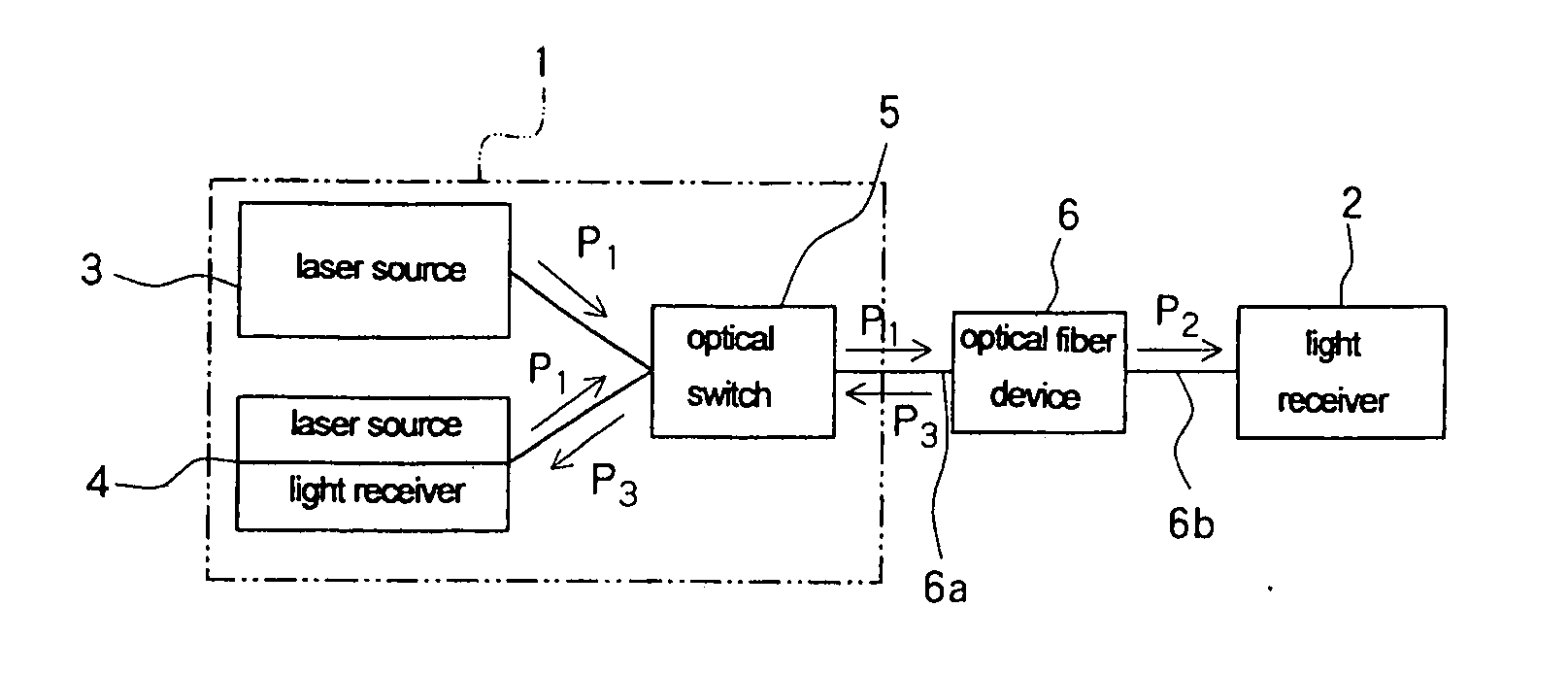
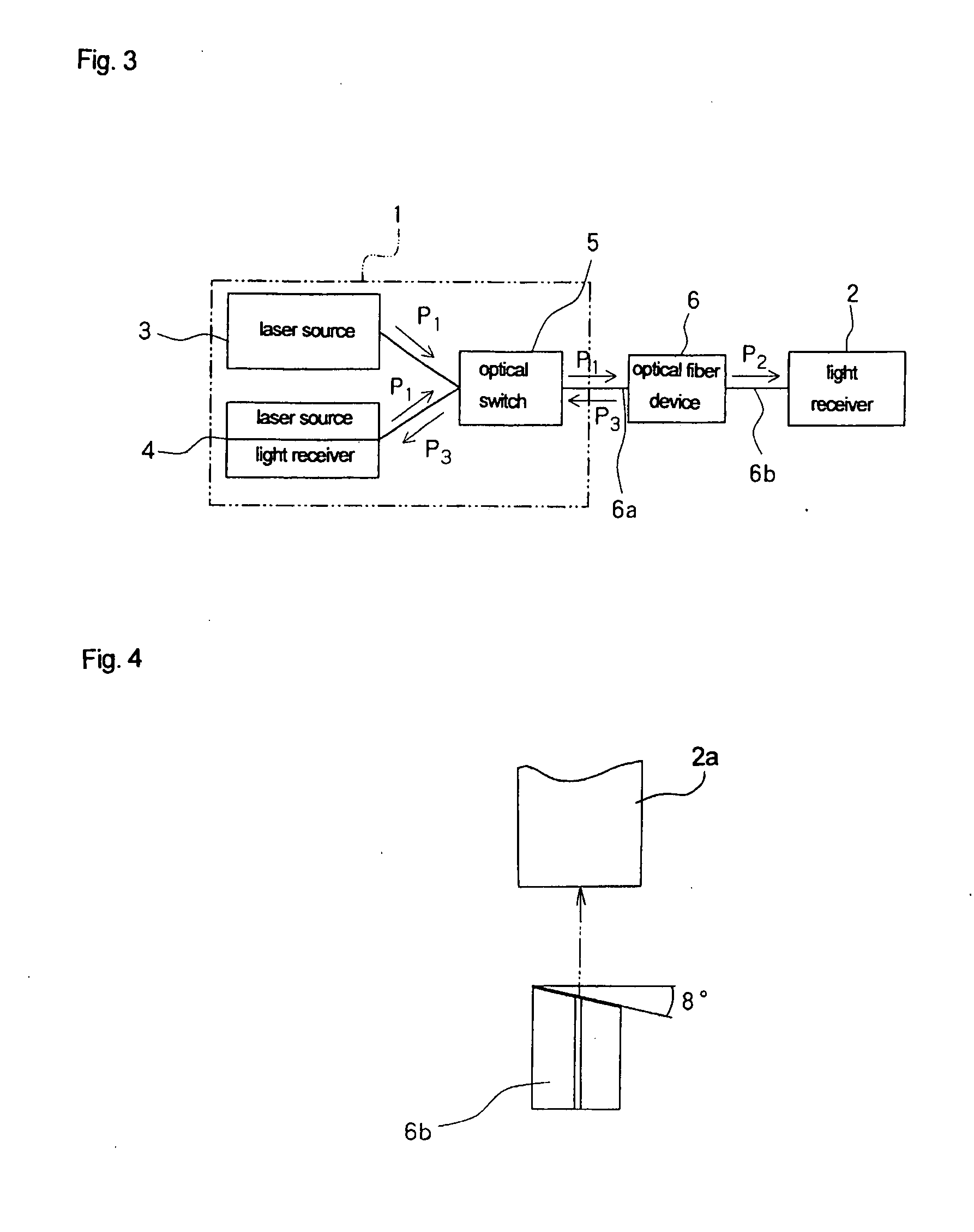
[0029]FIG. 3 shows an optical characteristic inspection apparatus for an optical fiber device according to the present invention. The inspections apparatus of the embodiment includes inspection unit 1 and light receiver (power meter) 2. Inspection unit 1 includes laser source 3 which is a light source for measuring loss, and reflection measuring module 4 containing a laser source used as a light source for measuring return loss and another light receiver (power meter). Both laser source 3 and reflection measuring module 4 are connected to optical switch 5.

[0030]When inspecting optical characteristics, input optical fiber 6a of single-core optical fiber device 6 to be inspected is connected to optical switch 5 of inspection unit 1, and output optical fiber 6b is connected to light receiver 2. The end of output optical fiber 6b is beveled before connecting to light receiver...


PUM

PropertyMeasurementUnit
angleaaaaaaaaaa
diameteraaaaaaaaaa
diameteraaaaaaaaaa

Abstract

An inspection unit, in which a laser source and a reflection measuring module containing a laser source and a light receiver are connected to an optical switch, is connected to an input optical fiber of an optical fiber device. An end of an output optical fiber is beveled and is connected to the light receiver through an adapter. When loss is measured, inspection light from the laser source is input into the light receiver through the input optical fiber, the optical fiber device, and the output optical fiber. When return loss is measured, an optical switch is switched to input inspection light, from the laser source in the reflection measuring module, into the optical fiber device through the input optical fiber, and to input light reflected from the optical fiber device into the light receiver in the reflection measuring module.

Description

BACKGROUND OF THE INVENTION[0001]1. Field of the Invention[0002]The present invention relates to an optical characteristic inspection method, an optical characteristic inspection apparatus, and an optical characteristic inspection system for an optical fiber device.[0003]2. Description of the Related Art[0004]The optical characteristics of an optical fiber device containing optical fibers must be inspected to check the performance of the optical fiber device after the process for adjusting the optical axes of the optical fibers with respect to each other, or after the process for adjusting the optical axes of functional components and the optical fibers and / or other functional components, or after the process for assembling the casing for enclosing the optical fiber device has been completed. In particular, measurement of loss caused while light is traveling through the optical fiber device and measurement of return loss caused when light enters the optical fiber device are commonly...

Claims


Application Information

Patent Timeline
Patent Type & Authority Applications(United States)
IPC IPC(8): G01N21/00
CPCG01M11/33G01M11/31
Inventor GOTO, MASANORIFUKAI, TSUTOMUONISHI, MASAHIRO
Owner SAE MAGNETICS (HK) LTD
Learn More