Monobore wellbore and method for completing same

a monobore and wellbore technology, applied in the direction of borehole/well accessories, drilling pipes, drilling rods, etc., can solve the problems of limited production, insufficient optimization of production resources, and inconvenient use of tubulars in conventional casing techniques, so as to minimize equipment size, maintain hydraulic and mechanical stability, and optimize available resources

Inactive Publication Date: 2006-07-11
HALLIBURTON ENERGY SERVICES INC
View PDF24 Cites 31 Cited by
  • Summary
  • Abstract
  • Description
  • Claims
  • Application Information

AI Technical Summary

Benefits of technology

[0009]The present invention disclosed herein comprises a monobore wellbore and method for providing a monobore wellbore that are capable of optimizing available resources while maintaining hydraulic and mechanical stability. The monobore wellbore and method of the present invention require a minimum number of sizes of casing and minimize the size of equipment near the surface. The monobore wellbore of the present invention achieves these results by expanding and coupling casing strings together to create a monobore with substantially one inner diameter.
[0012]To further extend the monobore wellbore, a third casing is passed through the first and second casings and is positioned within the wellbore such that an uphole end of the third casing is positioned within a second lap region of the second casing. Once expanded downhole, the third casing has an inner diameter substantially the same as the inner diameter of the second casing. The uphole end of the third casing is coupled to the second lap region of the second casing, thereby creating a monobore wellbore.

Problems solved by technology

It has been found, however, that each of these conventional casing techniques require multiple tubulars of decreasing diameters.
Accordingly, production resources are not optimized and production is limited by the diameter of the smallest tubular.

Method used


Image

  • Monobore wellbore and method for completing same
  • Monobore wellbore and method for completing same
  • Monobore wellbore and method for completing same

Examples


Embodiment Construction

[0031]While the making and using of various embodiments of the present invention are discussed in detail below, it should be appreciated that the present invention provides many applicable inventive concepts which can be embodied in a wide variety of specific contexts. The specific embodiments discussed herein are merely illustrative of specific ways to make and use the invention, and do not delimit the scope of the present invention.

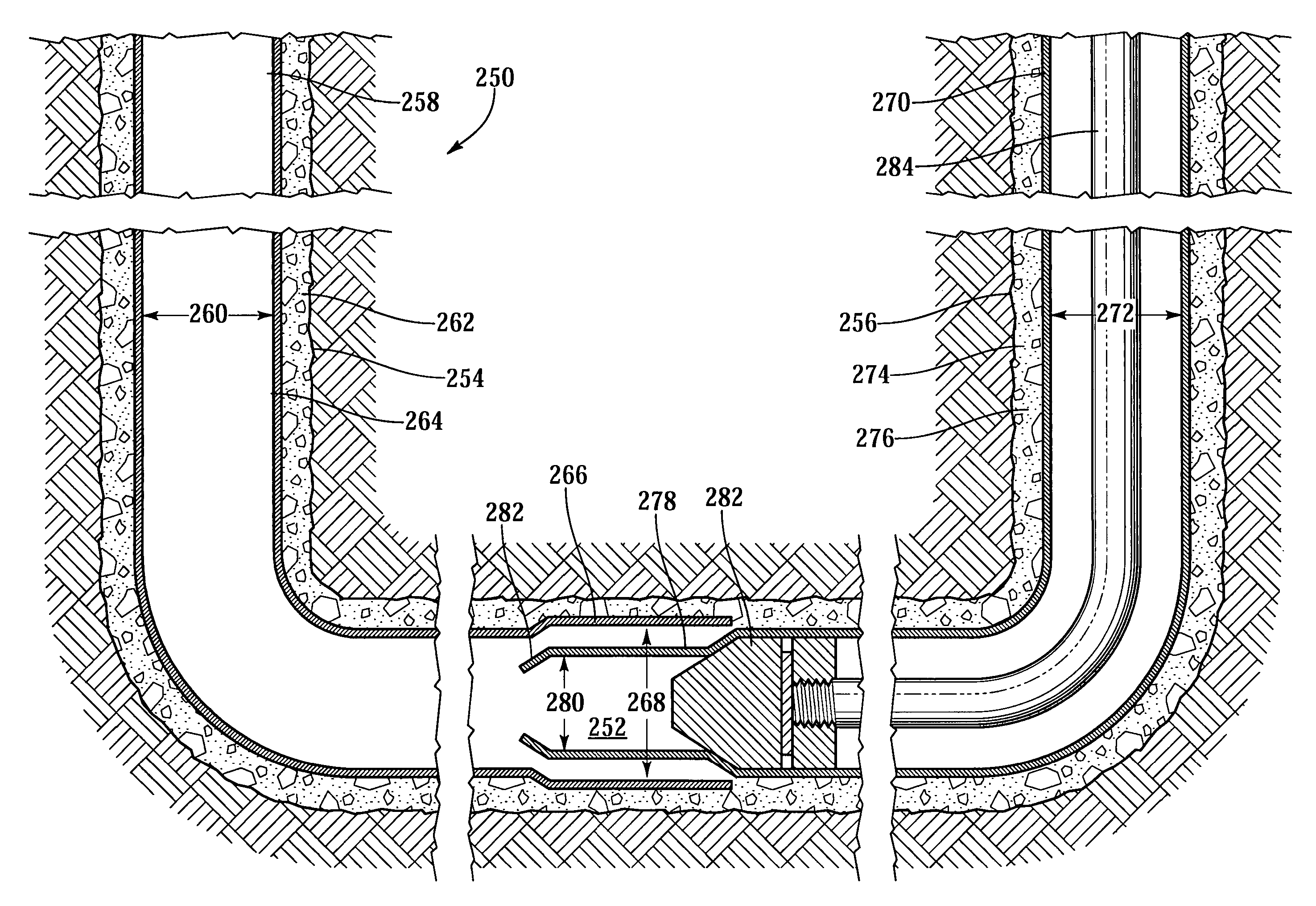
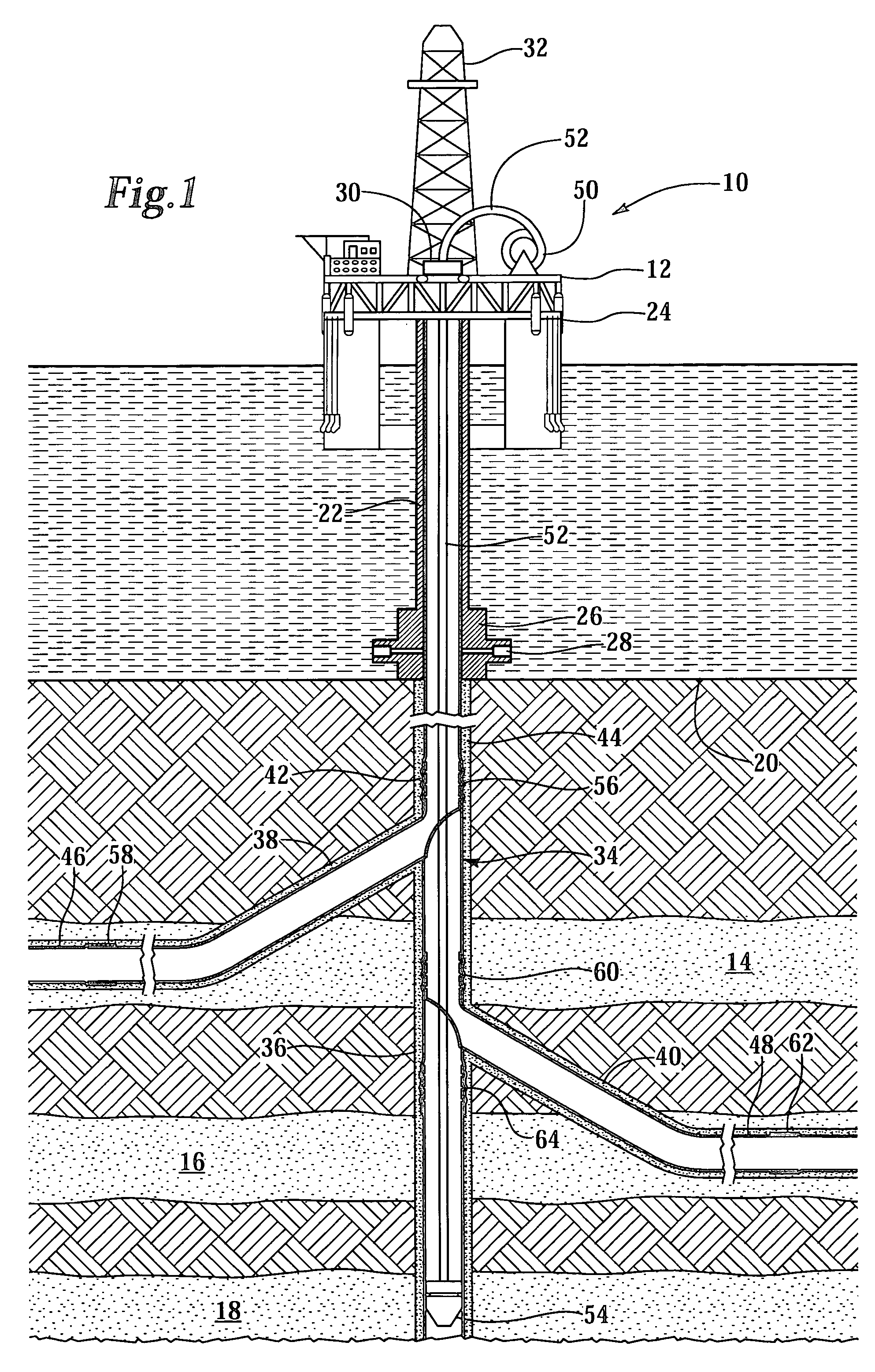
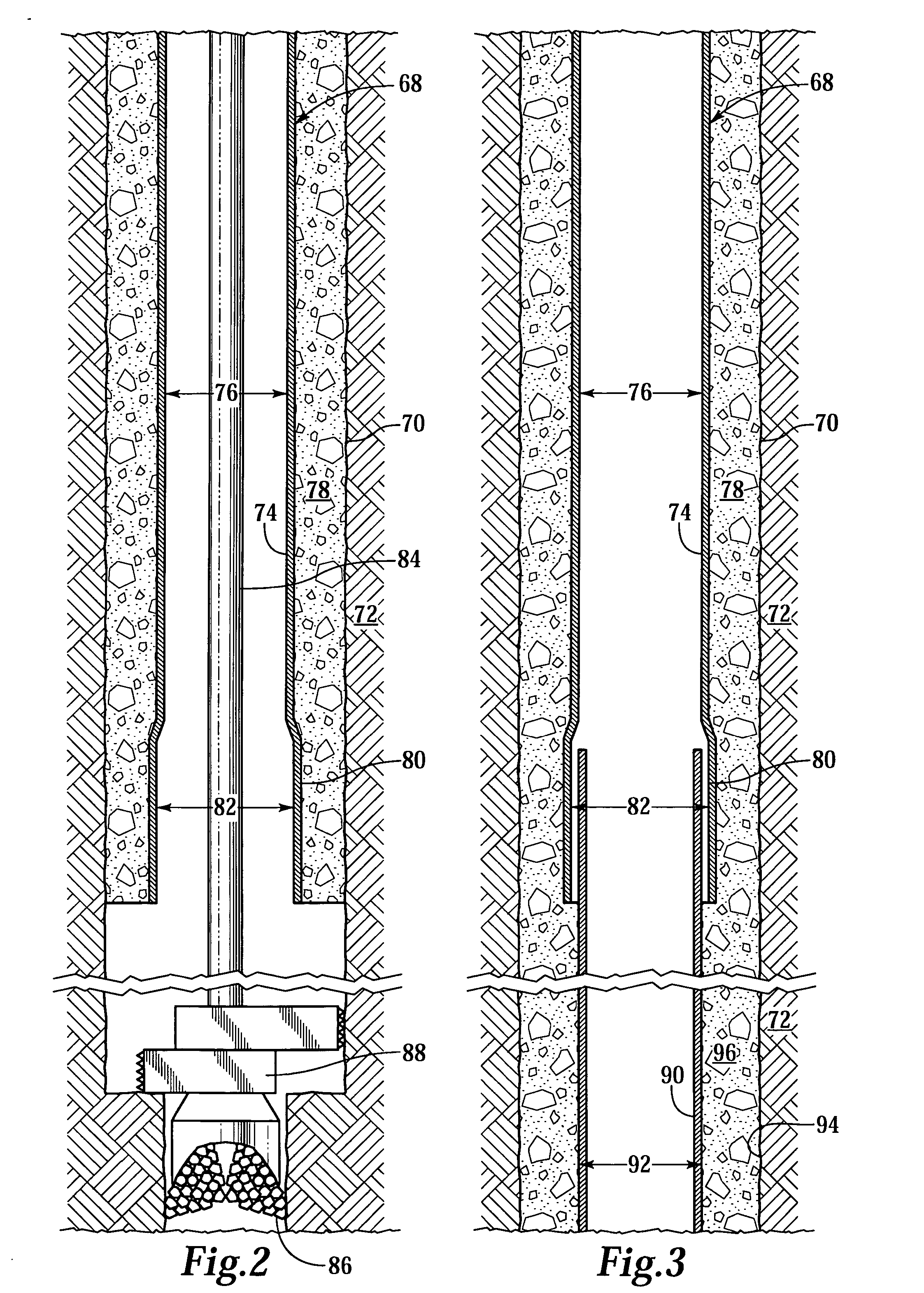
[0032]The present invention provides improved methods and apparatuses for creating a monobore wellbore. The methods can be performed in either vertical or horizontal wellbores. The term “vertical wellbore” is used herein to mean the portion of a wellbore in a producing zone to be completed which is substantially vertical, inclined or deviated. The term “horizontal wellbore” is used herein to mean the portion of a wellbore in a subterranean producing zone, which is substantially horizontal. Since the present invention is applicable in vertical, horizonta...


PUM


Abstract

A monobore wellbore (68) and method for completing the same are disclosed. The monobore wellbore (68) comprises a first casing (74) having an inner diameter (76) and a lap region (80). A second casing (90) is positioned within the wellbore (70) by passing through the first casing (74) such that an uphole end of the second casing (90) is positioned within the lap region (80) of the first casing (74). After downhole expansion, the second casing (90) has an inner diameter (114) that is substantially the same as the inner diameter (76) of the first casing. The uphole end of the second wellbore is coupled to the lap region (80) of the first casing (74) to create a mechanical connection and a hydraulic seal, thereby creating the monobore wellbore (68).

Description

CROSS-REFERENCE TO RELATED APPLICATIONS[0001]This is a continuation-in-part application of application Ser. No. 10 / 103,381 now U.S. Pat. No. 6,749,026, entitled Downhole Tubular String Connection, filed on Mar. 21, 2002.TECHNICAL FIELD OF THE INVENTION[0002]This invention relates, in general, to completing a well that traverses a hydrocarbon bearing subterranean formation, and, in particular, to a monobore wellbore or multilateral monobore wellbore and method for completing the same by expanding and coupling portions of the casing downhole.BACKGROUND OF THE INVENTION[0003]Without limiting the scope of the present invention, its background will be described with reference to producing fluid from a subterranean formation, as an example.[0004]After drilling each of the sections of a subterranean wellbore, individual lengths of relatively large diameter metal tubulars are typically secured together to form a casing string that is positioned within each section of the wellbore. This casi...

Claims


Application Information

Patent Timeline
Patent Type & Authority Patents(United States)
IPC IPC(8): E21B17/00E21B17/08E21B29/00E21B41/00E21B43/10E21B43/30
CPCE21B17/08E21B29/00E21B43/30E21B43/103E21B43/106E21B41/0042E21B43/10E21B43/14
Inventor SMITH, RAY C.
Owner HALLIBURTON ENERGY SERVICES INC
Why Eureka
Try Eureka