Power tool

Inactive Publication Date: 2006-07-11
BLACK & DECKER INC
View PDF25 Cites 13 Cited by
  • Summary
  • Abstract
  • Description
  • Claims
  • Application Information

AI Technical Summary

Benefits of technology

[0009]The present invention aims to provide a hand held power tool in which the number of

Problems solved by technology

The problem with circlips is that they are difficult to correctly assemble onto the hammer spindle or mode change sleeve.
If the circlip is not correctly assembled then the axial stop is not effective and the hammer will not operate correctly.
A

Method used


Image

  • Power tool
  • Power tool
  • Power tool

Examples


Example

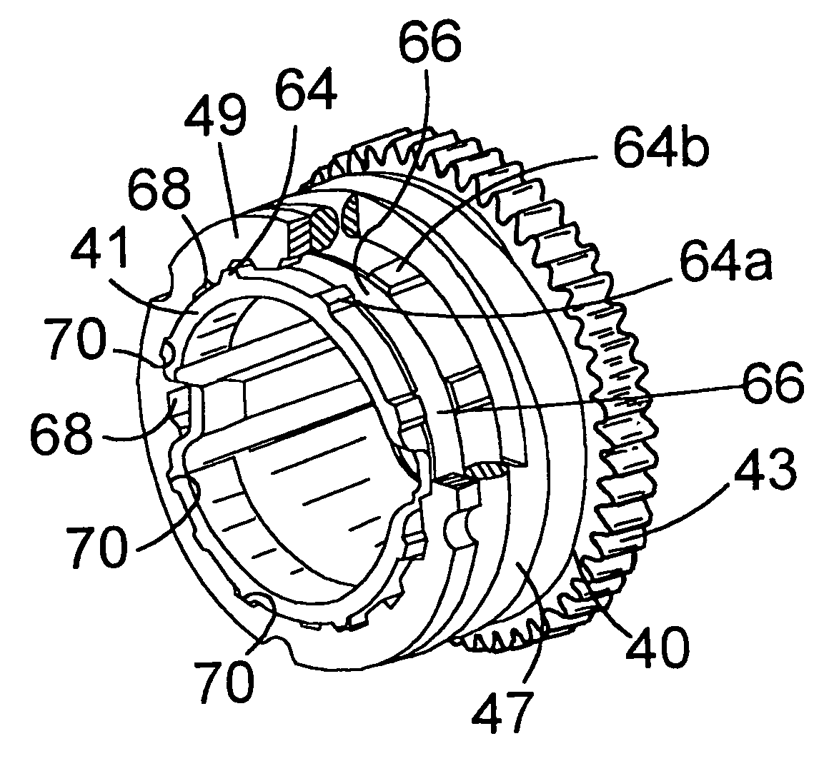
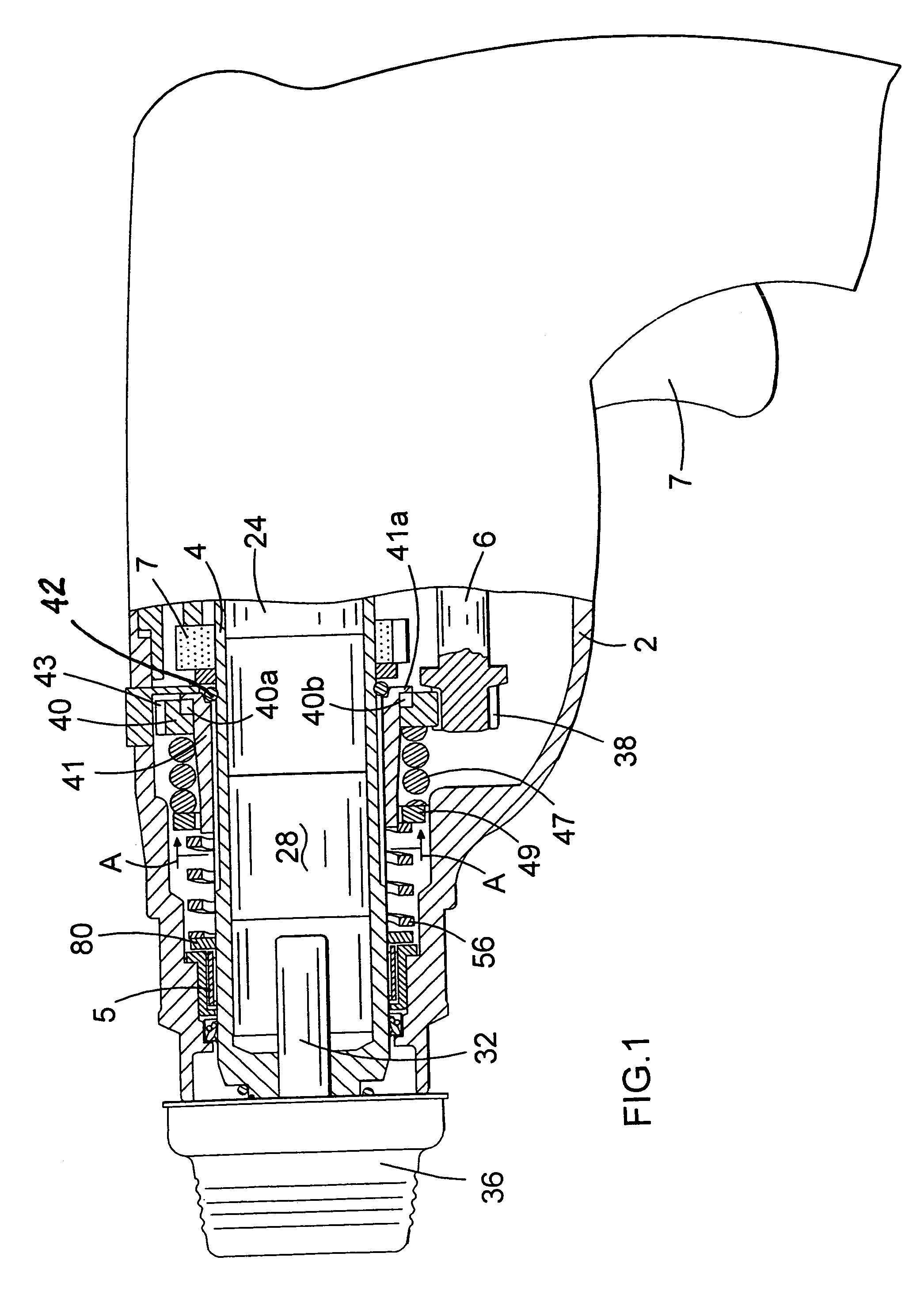
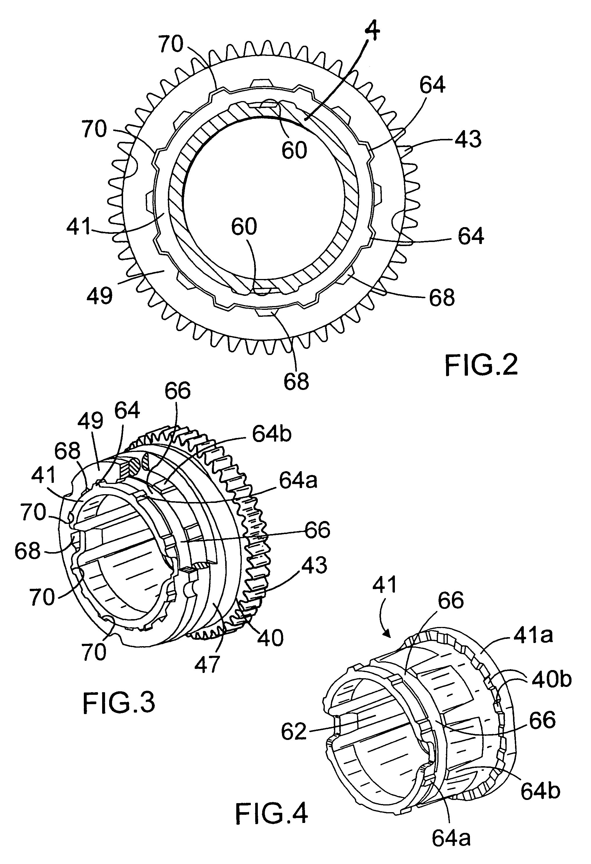
[0032]The rotary hammer has a forward portion which is shown in cross-section in FIG. 1 and a rearward portion incorporating a motor and a pistol grip rear handle (shown cut away), in the conventional way. Alternatively, the handle may be of the D-handle type. The handle portion incorporates a trigger switch (7) for actuating the electric motor, which motor is formed at the forward end of its armature shaft with a pinion. The pinion of the motor rotatingly drives an intermediate shaft (6) via a gear which gear is press fit onto the rearward end of the intermediate shaft (6). The intermediate shaft is rotatingly mounted in the housing (2) of the hammer via a pair of bearings (not shown).

[0033]A wobble drive hammering mechanism, of a type that is well known in the art, is provided for reciprocatingly driving a piston (24). The piston (24) is slideably located within the hollow cylindrical spindle (4) and an O-ring seal is mounted around the piston (24) so as to seal between the periph...


PUM

PropertyMeasurementUnit
Forceaaaaaaaaaa

Abstract

A portable tool comprising a spindle defining a longitudinal axis, a spring extending around the spindle in the axial direction for biasing a component of the tool, a stop ring extending around the spindle and against which the spring bears. The spindle includes a plurality of circumferentially spaced radially outward projections and the stop ring includes on its internal surface a corresponding plurality of recesses extending from the bearing face of the stop ring to an opposite face, and a corresponding plurality of pockets open at the opposite face. During assembly, the stop ring is fitted over the spindle or sleeve by the passing the recesses over the projections and then rotating the stop ring to align the pockets with projections. The stop ring is axially fixed on the spindle by the pockets engaging the projections under the biasing force from the spring.

Description

[0001]This invention relates to hand-held powered tools, in particular electrically powered tools having a rotatingly driven spindle for driving a tool or bit.BACKGROUND OF THE INVENTION[0002]Many types of hand held power tools are known which have a rotatingly driven spindle via which a tool or bit is rotatingly driven. One example of such a power tool is a rotary hammer having a hollow spindle within which an air cushion hammering mechanism is at least partly located.[0003]Rotary hammers are known which have a housing and a hollow cylindrical spindle rotatably mounted in the housing. The spindle allows insertion of the shank of a tool or bit, for example a drill bit or a chisel bit, into the front end thereof so that it is retained in the front end of the spindle with a degree of axial movement. The spindle may be a single cylindrical part or may be made of two or more cylindrical parts, which together form the hammer spindle. For example, a front part of the spindle may be formed...

Claims


Application Information

Patent Timeline
IPC IPC(8): B25D17/00B25D16/00B25F5/00F16B21/02
CPCB25D16/003B25D16/006B25F5/001B25D2250/165B25D2250/225F16B21/02B25D2250/331B25D2250/335B25D2250/235
Inventor DROSTE, MANFRED
Owner BLACK & DECKER INC
Why Eureka
Try Eureka