Golf ball

Inactive Publication Date: 2006-07-11
ACUSHNET CO
View PDF48 Cites 64 Cited by
  • Summary
  • Abstract
  • Description
  • Claims
  • Application Information

AI Technical Summary

Benefits of technology

[0013]At least one outermost core layer has a specific gravity of greater than 1.25 g/cc, preferably greater than 1.50 g/cc, and most preferably greater than 1.75 g/cc therein increasing the moment of inertia of the overall golf ball and thereby lowering the spin rates. This outermost core layer may be heavily filled with density increasing material while the center and any intermediate core layers may be filled with a density reducing material, preferably greater than 2 g/cc, more preferably greater than 5 g/cc and most preferably greater than 10 g/cc.
[0014]The invention also provides for a single core layer to serve all the above functions: stiffness grea

Problems solved by technology

On the other hand, the recreational players who cannot intentionally control the spin of the ball generally do not prefer a high spin rate golf ball.
When a club head strikes a ball improperly, an unintentional side spin is often imparted to the ball, which sends the ball off its intended course.
The side spin reduces a player's control over the

Method used


Image

  • Golf ball
  • Golf ball
  • Golf ball

Examples


Embodiment Construction

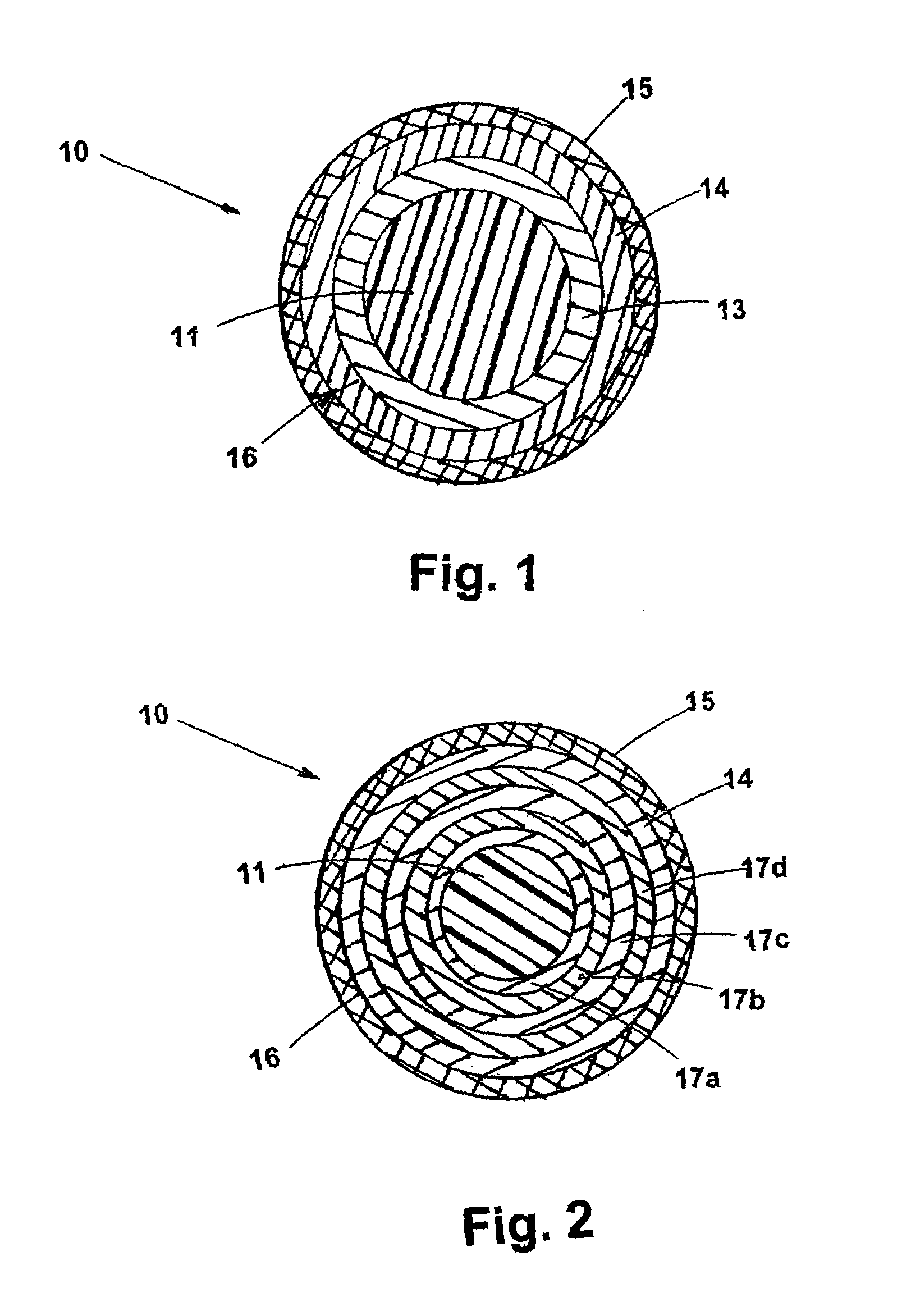
[0031]Referring to FIGS. 1 and 2, golf ball 10 includes a core 16 and a cover 15. Core 16 includes a center 11, and at least one core layer. FIG. 1 depicts an embodiment of the invention having two outer core layers, an intermediate core layer 13 and a relatively rigid outermost core layer 14. However, FIG. 2 describes an embodiment having five core layers. They are: a first intermediate core layer 17a, a second intermediate core layer 17b, a third intermediate core layer 17c, a fourth intermediate core layer 17d, and a fifth core layer which is generally very rigid, also referred to as the outermost core layer 14.

[0032]Referring to FIG. 2, the center 11 is preferably formed by compression molding a sphere from a prep of center material. Compression molding solid centers is well known in the art.

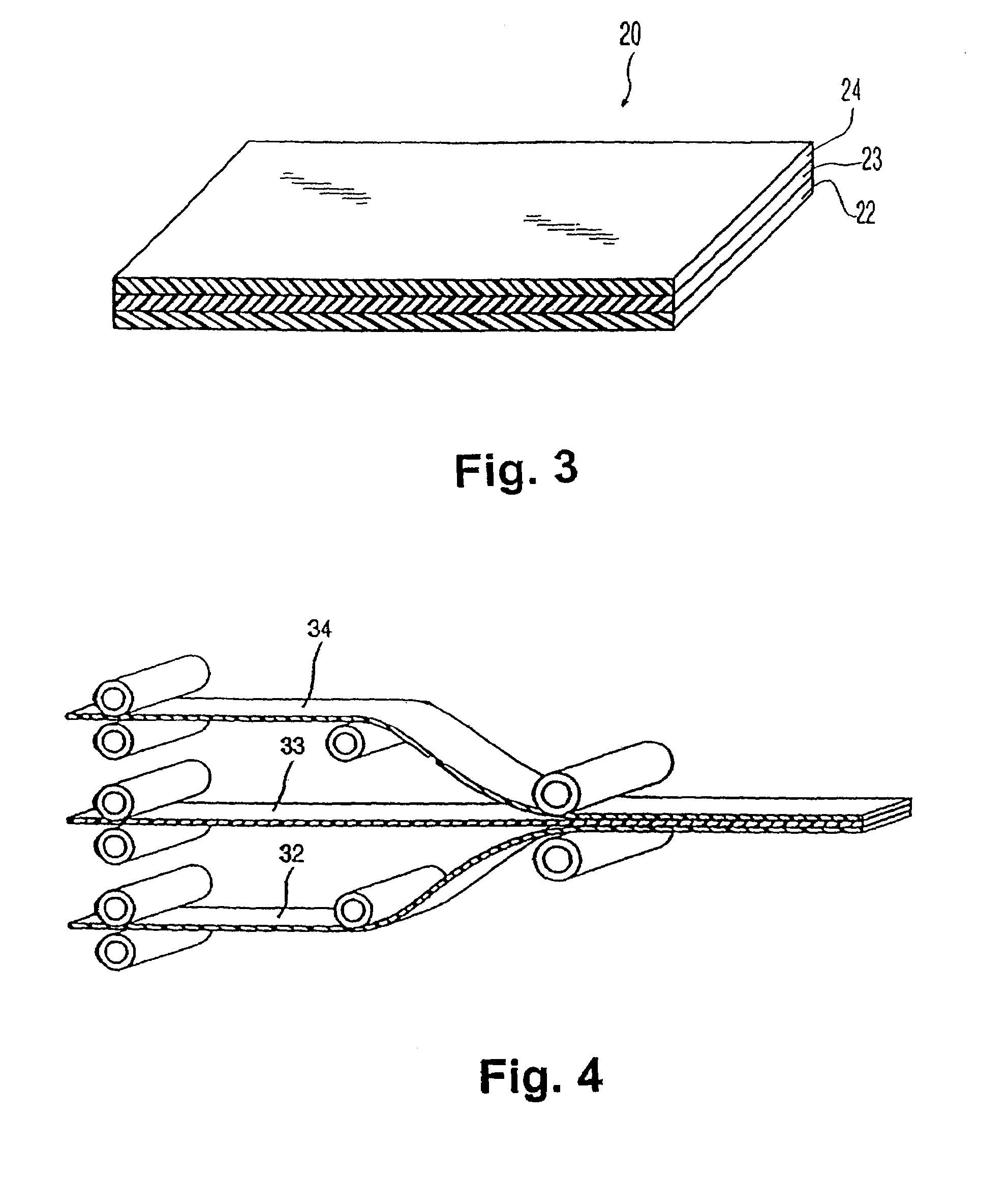
[0033]Referring to FIGS. 3 and 4, in order to form multiple layers around the center in a first embodiment of the invention, preferably a laminate 20 is formed. The laminate 20 is comprised ...


PUM

PropertyMeasurementUnit
Lengthaaaaaaaaaa
Lengthaaaaaaaaaa
Lengthaaaaaaaaaa

Abstract

The present invention is directed towards a multi-layered core golf ball that comprises a thermoplastic inner casing layer molded between two polybutadiene core layers to create a faster golf ball with less spin, by designing a ball that has more of the stored energy of the core released at impact. One inner casing layer and/or an outer core layer is comprised of a partially or fully neutralized ionomer.

Description

CROSS REFERENCE TO RELATED APPLICATIONS[0001]This application is a continuation-in-part of U.S. patent application Ser. No. 10 / 797,699, filed Mar. 10, 2004, now U.S. Pat. No. 6,981,926, which is a continuation-in-part of U.S. patent application Ser. No. 10 / 341,574, filed Jan. 13, 2003, now U.S. Pat. No. 6,852,044, which is a continuation-in-part of U.S. patent application Ser. No. 10 / 002,641, filed Nov. 28, 2001, now U.S. Pat. No. 6,547,677, which is a continuation-in-part of U.S. patent application Ser. No. 09 / 948,692, filed Sep. 10, 2001, now U.S. Pat. No. 7,014,573, which is a continuation-in-part of U.S. patent application Ser. No. 09 / 172,608, filed Oct. 18, 1998, now U.S. Pat. No. 6,302,808, which is a division of U.S. patent application Ser. No. 08 / 943,932, filed Oct. 3, 1997, now U.S. Pat. No. 6,056,842; also the application is a continuation-in-part of U.S. patent application Ser. No. 09 / 815,753, filed Mar. 23, 2001, now U.S. Pat. No. 6,494,795, the disclosures of which are ...

Claims


Application Information

Patent Timeline
IPC IPC(8): A63B37/06A63B37/00A63B37/02A63B37/04A63B45/00B29C43/14B29C43/18B29C43/30B29C70/70B29D99/00B32B7/022
CPCA63B37/0003B32B27/30A63B37/0037A63B37/0043A63B37/0047A63B37/0049A63B37/0065A63B37/0066A63B37/0076A63B37/02A63B37/04B29C43/027B29C43/146B29C43/18B29C51/267B29C70/70B29D99/0042B32B1/00B32B25/08B32B25/16B32B27/06B32B27/20A63B37/0031A63B37/0061A63B45/00B29C43/305B29C49/02B29C49/20B29C51/14B29C63/22B29C2043/3644B29C2791/001B29C2791/006B29K2105/256B29L2009/00B29L2031/52B29L2031/54B29L2031/545B32B7/022B32B27/40B32B27/08B32B2309/105B32B2307/546B32B2307/536B32B2375/00
Inventor SULLIVAN, MICHAEL J.LADD, DEREK A.DESIMAS, ANTONIO U.
Owner ACUSHNET CO
Why Eureka
Try Eureka