Lighting ballast having boost converter with on/off control and method of ballast operation

a technology of on/off control and ballast, applied in the field of lighting ballast, can solve the problems of affecting the operation of switching transistors, and consuming approximately 5 watts of input power in typical prior art electronic ballasts. , to achieve the effect of reducing the power consumption of electronic dimming ballast and reducing the boosted voltage level

Active Publication Date: 2006-07-11
LUTRON TECH CO LLC
View PDF4 Cites 73 Cited by
  • Summary
  • Abstract
  • Description
  • Claims
  • Application Information

AI Technical Summary

Benefits of technology

[0006]According to the invention, a ballast for a lighting load is provided having a boost converter for converting a rectified AC input voltage into a DC bus voltage. The DC bus voltage is provided to an inverter output stage for driving the lighting load. According to the invention, in order to save energy, particularly when the lighting load is dimmed below a specified dimming level, the boost converter is turned off, thereby dissipating less power. When the boost converter is turned off, the DC bus voltage drops to essentially the peak value of the rectified AC input voltage. Because the lighting load has been dimmed, the higher bus voltage required at higher light levels is not necessary. By turning the boost converter off, in the example given of the ballast consuming approximately 5 watts of power at the low end dimming level, approximately 1.5 watts of power is saved due to eliminating switching losses in the boost converter. Accordingly, about 25% of the loss in the ballast at low end lighting levels has been eliminated by the invention.
[0009]According to another aspect, the invention comprises a method for reducing the power consumption of an electronic dimming ballast for a lighting load comprising receiving an alternating current input having a peak voltage level and providing a direct current voltage output having a boosted voltage level that is greater than the peak voltage level of the alternating current input, converting the direct current voltage output into a high-frequency AC voltage for driving the lighting load in an output stage, receiving a desired light level input corresponding to a desired light level of the lighting load and dimming the lighting load based on the desired light level, and reducing the boosted voltage level to a reduced voltage level when the desired light level input drops to a first specified desired light level.

Problems solved by technology

Typical prior art electronic ballasts may consume approximately 5 watts of input power at the low end dimming level in the ballast.
However, the switching transistor typically has switching losses associated with its operation.
These switching losses are a fairly insignificant proportion of the total power consumed by the ballast and the load when the load is at high end.
However, at low end, the improvements in THD and power factor are not as important because the line current drawn by the ballast and the load is much lower.

Method used


Image

  • Lighting ballast having boost converter with on/off control and method of ballast operation
  • Lighting ballast having boost converter with on/off control and method of ballast operation
  • Lighting ballast having boost converter with on/off control and method of ballast operation

Examples


Embodiment Construction

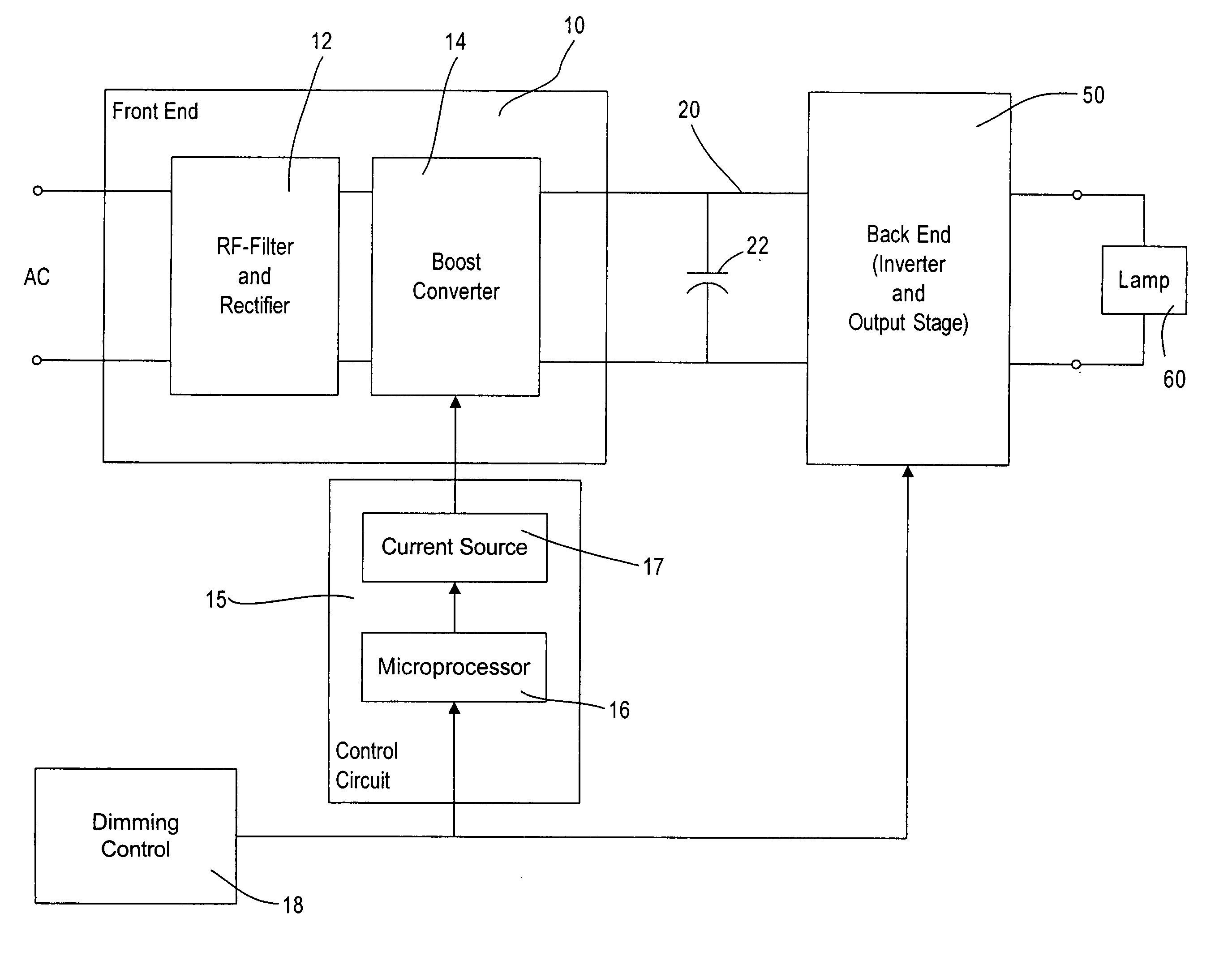
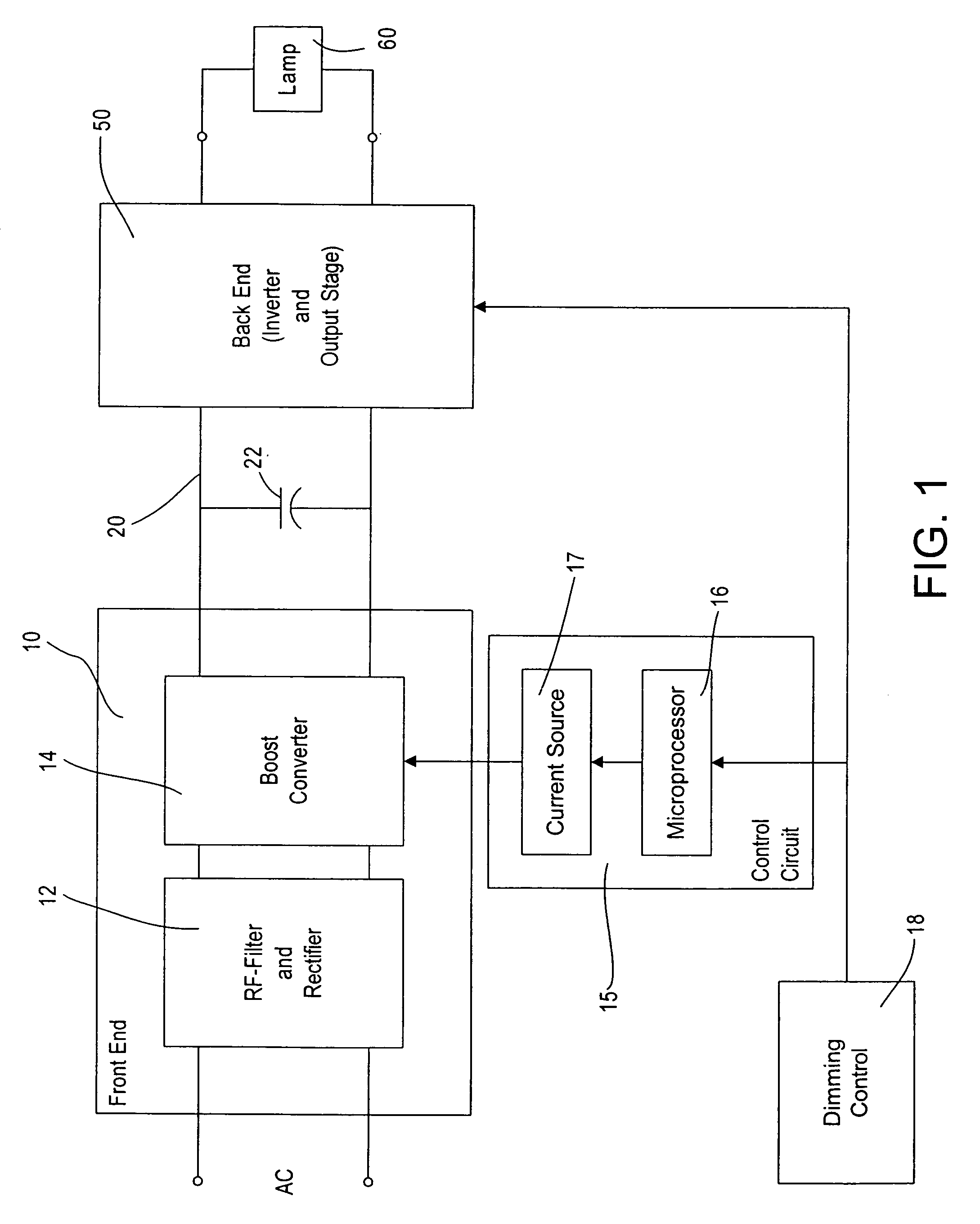
[0021]With reference now to the drawings, FIG. 1 shows a block diagram of the dimming ballast according to the present invention. The ballast has a front end circuit 10 and a back end circuit 50. The back end circuit, including an inverter circuit and an output stage, drives a lamp or lamps 60, for example, fluorescent lamps, high-energy discharge lamps, or other suitable lighting loads.

[0022]The front end circuit 10 receives an input from an AC supply, for example 277 volts RMS at 60 Hz. However, any suitable AC input voltage and line frequency can be supplied to power the ballast. The AC input is provided to an RF filter and rectifier stage 12, for example, an EMI filter stage and a full-wave rectifier, as well known to those of skill in the art. The output of the RF filter and rectifier stage 12 is fed to a boost converter stage 14 that is controlled by a control circuit 15, including a microprocessor 16 and a switchable current source 17. The microprocessor 16 receives an input ...


PUM


Abstract

A ballast for driving a gas discharge lamp comprising a rectifier stage having an alternating current (AC) input and providing a rectified output voltage, a boost converter stage receiving the rectified output voltage as an input and providing a boosted direct current (DC) output voltage across a DC bus, an inverter output stage for converting the DC bus voltage to a high-frequency AC output voltage to drive the lamp, further comprising a control stage receiving a desired light level signal controlling the desired light level of the lamp and providing an output control signal for turning the boost converter stage on or off in dependency on the desired light level signal. The ballast thereby has reduced power consumption at low light levels for greater energy efficiency.

Description

BACKGROUND OF THE INVENTION[0001]The present invention relates to a lighting ballast, in particular, to an electronic dimming ballast having a front end having an input coupled to an alternating current (AC) supply and having an output supplying a direct current (DC) bus that feeds a back end powering a lighting load, for example, a gas discharge lamp load such as a fluorescent lamp or other lamp load.[0002]There is an increasing need to maximize the efficiency of electronic ballasts. In particular, in electronic dimming ballasts, the total energy consumed is the combination of the energy consumed by the electronic circuitry of the ballast and the energy consumed by the lighting load. In particular, as the lighting load is dimmed to lower levels, the energy consumed by the circuitry of the ballast comprises a greater proportion of the total energy consumed. The proportion of energy consumed by the ballast is typically greatest at the lowest dimming level. It is desirable, therefore,...

Claims


Application Information

Patent Timeline
Patent Type & Authority Patents(United States)
IPC IPC(8): G05F1/00
CPCH05B41/282H05B41/3921H05B41/3927Y10S315/05Y02B20/183Y10S315/07Y02B20/00
Inventor CHITTA, VENKATESHGAWRYS, BRENT M.
Owner LUTRON TECH CO LLC
Why Eureka
Try Eureka