System for damage location using a single channel continuous acoustic emission sensor

a continuous acoustic emission and sensor technology, applied in the field of non-destructive testing, can solve the problems of inability to efficiently integrate into composite and heterogeneous structures, laborious non-destructive evaluation techniques, and loss of the entire vehicle,

Inactive Publication Date: 2006-07-11
NORTH CAROLINA AT&T STATE UNIV
View PDF9 Cites 56 Cited by
  • Summary
  • Abstract
  • Description
  • Claims
  • Application Information

AI Technical Summary

Benefits of technology

[0015]Also, in the preferred embodiment, the signal processing module includes an input, a filter and an output on a timed scale to calculate the location of the critical structural event. The filter may be at a predetermined band width and, in the preferred embodiment, the predetermined band width is calculated according to the Lamb wave propagation characteristics resulting from the acoustic emission pulse at the source location and by identifying one or more non dispersive modes of this lamb wave to locate this acoustic emission source. Alternatively, it may be calculated using an electronic tag attached to each sensor that provides the ID number of the first hit sensor. The data collection system may include a database module. In addition, the data collection system may further include an exception reporting module. In the preferred embodiment, the exception reporting module includes means for setting a predetermined threshold value and means for sending an alarm when the predetermined threshold value is met. Also, the exception reporting module may further include means for identifying the location of the alarm.

Problems solved by technology

There has been a reluctance to deploy such high performance materials in critical structural applications because of their susceptibility to in-service damage.
The damage occurring in these materials may be difficult to track and can propagate quickly during operation of the vehicle or structure, resulting in the loss of the entire vehicle.
Conventional non-destructive evaluation techniques are labor intensive, expensive, error prone, and unworkable for efficient integration into composite and heterogeneous structures.
When the structural geometry is complex—e.g., either the structure has varying thickness, curvature, ribs, joints, or heterogeneous materials, or damage is located near boundaries of the structure—it becomes difficult to detect small damage using SHM methods.
In addition, the number of sensor circuits and computations required increases the overall complexity and cost of the structure.
However, fiber optic sensors have limitations when applied to monitoring complex composite structures where damage can occur anywhere on the structure and in any direction.
For example, discrete strain measurements can miss damage because the measurement is very localized at the fiber / grating.
In addition, an optical analyzer using multiplexing and multiple connections is expensive; measurements are not simultaneous and the frequency bandwidth may be too low to sense Acoustic Emission (AE) signals.
However, present passive acoustic emission and monitoring techniques require bulky instrumentation with numerous channels, long connections, and centralized data analysis.
It may be impractical to embed these systems on the structure to operate in the field.
Another limitation is that AE waveforms from such sensors are too complicated for purposes of source characterization.

Method used


Image

  • System for damage location using a single channel continuous acoustic emission sensor
  • System for damage location using a single channel continuous acoustic emission sensor
  • System for damage location using a single channel continuous acoustic emission sensor

Examples


Embodiment Construction

[0034]In the following description, like reference characters designate like or corresponding parts throughout the several views. Also in the following description, it is to be understood that such terms as “forward,”“rearward,”“left,”“right,”“upwardly,”“downwardly,” and the like are words of convenience and are not to be construed as limiting terms.

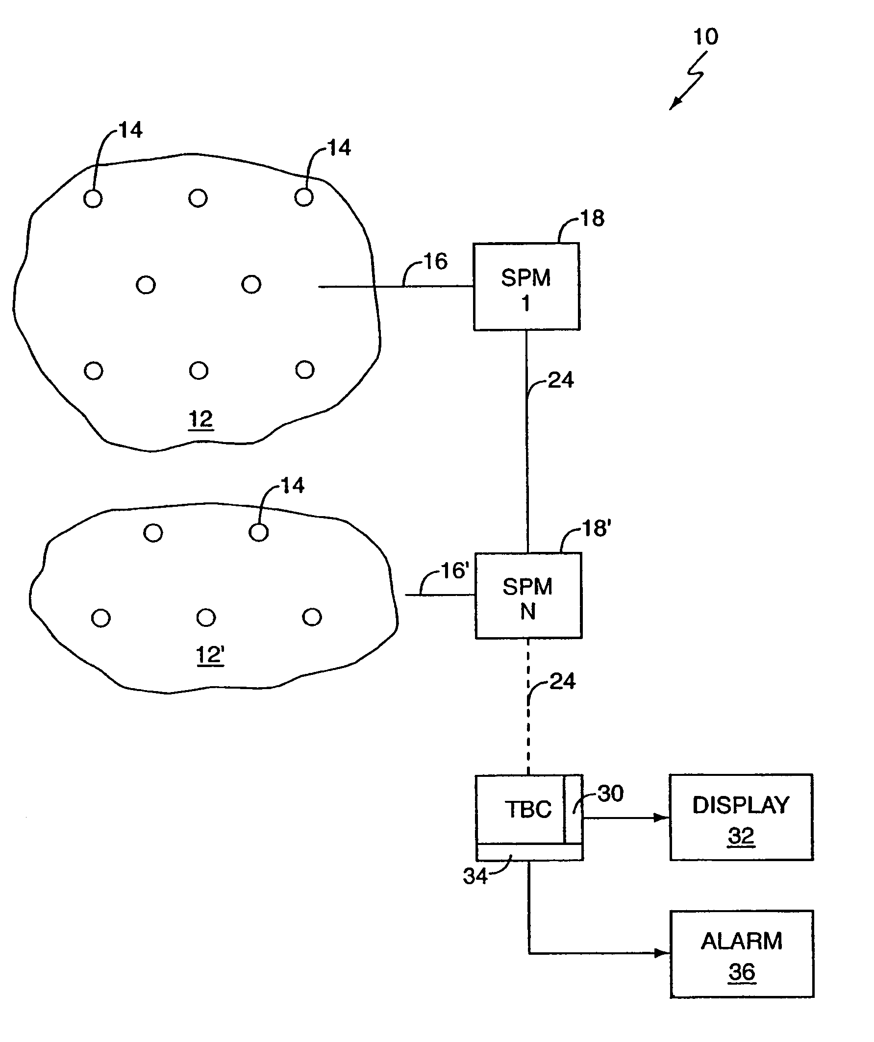
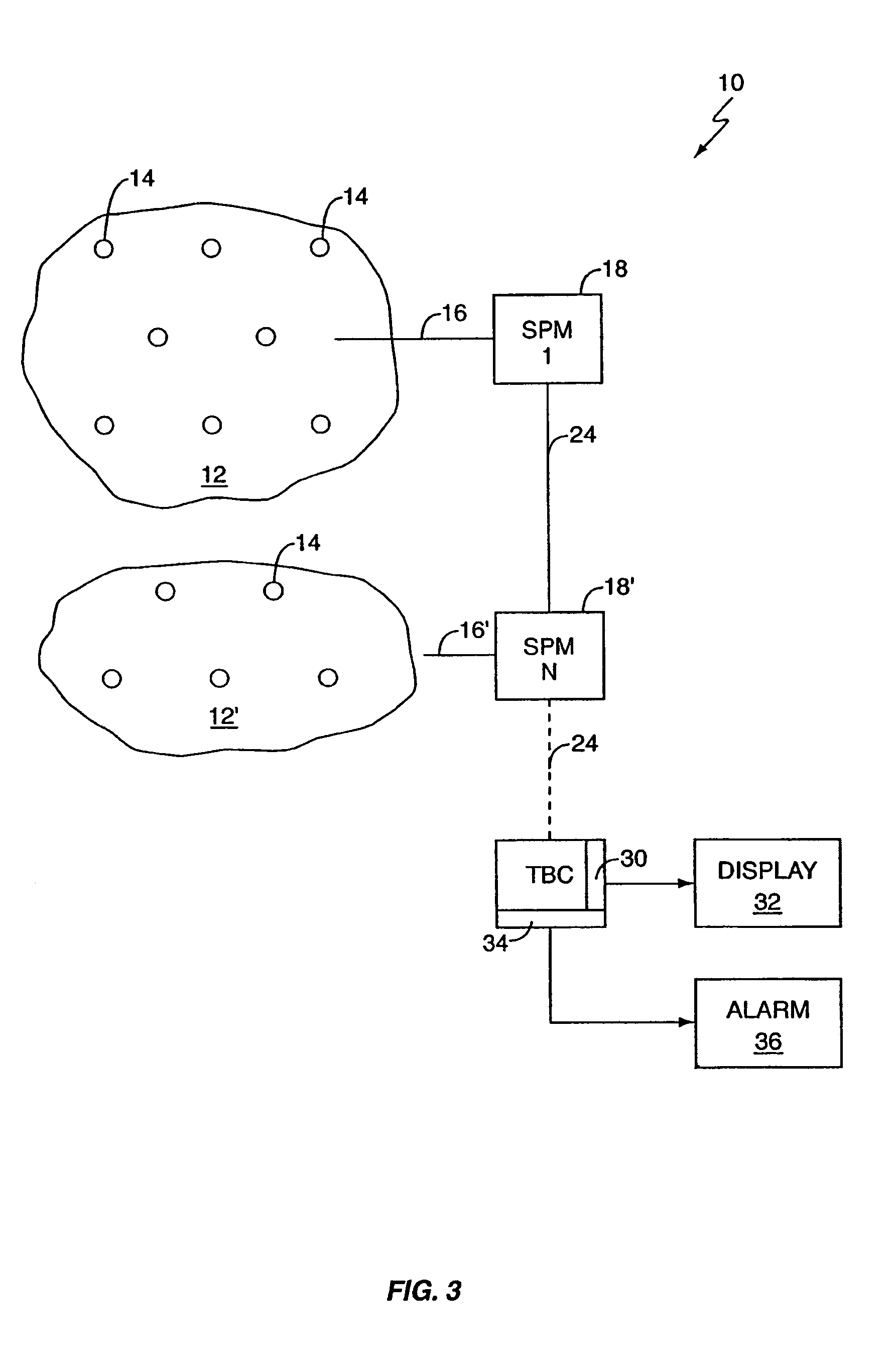
[0035]Referring now to the drawings in general and FIG. 3 in particular, it will be understood that the illustrations are for the purpose of describing a preferred embodiment of the invention and are not intended to limit the invention thereto. As best seen in FIG. 3, a sensor array, generally designated 10, is shown constructed according to the earlier invention disclosed in commonly owned U.S. Pat. No. 6,399,939. The sensor array 10 includes three major sub-assemblies: a unit cell 12 having a plurality of discrete sensor nodes 14; a signal adder for combining the output of each of the discrete sensor nodes 14 into a single output 16; a...


PUM


Abstract

A sensor array for non-destructively monitoring a structure to detect a critical structural event. The sensor array includes a plurality of discrete sensor nodes, each of the discrete sensor nodes producing an electrical signal in response to a structural event. A signal adder is electrically connected to the plurality of discrete sensor nodes for receiving and combining the electrical signal from each of the discrete sensor nodes to form a single sensor array output signal. A signal processing module then receives and processes the single sensor output signal. In the preferred embodiment, the signal processing module uses the time interval between the electrical signals from each of the discrete sensor nodes formed into a single sensor array output signal to calculate the location of the critical structural event. Also, in the preferred embodiment, a data collection system is located downstream of the sensor processing module.

Description

BACKGROUND OF THE INVENTION[0001](1) Field of the Invention[0002]The present invention relates generally to non-destructive testing and, more particularly, to a sensor array for non-destructively monitoring a structure to detect a critical structural event and calculate the location of the critical structural event.[0003](2) Description of the Prior Art[0004]The performance of modern-day military helicopters, missiles, tanks, aircraft, and other static or dynamic structures is critically dependent on the reliability of advanced composite materials and heterogeneous armor materials. There has been a reluctance to deploy such high performance materials in critical structural applications because of their susceptibility to in-service damage. The damage occurring in these materials may be difficult to track and can propagate quickly during operation of the vehicle or structure, resulting in the loss of the entire vehicle.[0005]Conventional non-destructive evaluation techniques are labor...

Claims


Application Information

Patent Timeline
Patent Type & Authority Patents(United States)
IPC IPC(8): G08B23/00
CPCG01N29/14G01N29/2406G01N29/245G01N29/44G01N29/4463G01N2291/2694G01N2291/0427G01N2291/044G01N2291/106
Inventor SUNDARESAN, MANNUR J.GHOSHAL, ANINDYASCHULZ, MARK J.
Owner NORTH CAROLINA AT&T STATE UNIV
Why Eureka
Try Eureka