Vehicle speed sensor for navigation system

a technology of speed sensor and navigation system, which is applied in the direction of distance measurement, navigation instruments, instruments, etc., can solve the problems of cost or inconvenient connection to these systems

Inactive Publication Date: 2006-07-11
DIDI HK SCI & TECH LTD
View PDF26 Cites 30 Cited by
  • Summary
  • Abstract
  • Description
  • Claims
  • Application Information

AI Technical Summary

Problems solved by technology

Since vehicles' electrical control systems are not standardized, it is often costly or inconvenient to connect to these systems when installing a navigation system in the vehicle.

Method used


Image

  • Vehicle speed sensor for navigation system
  • Vehicle speed sensor for navigation system

Examples


second embodiment

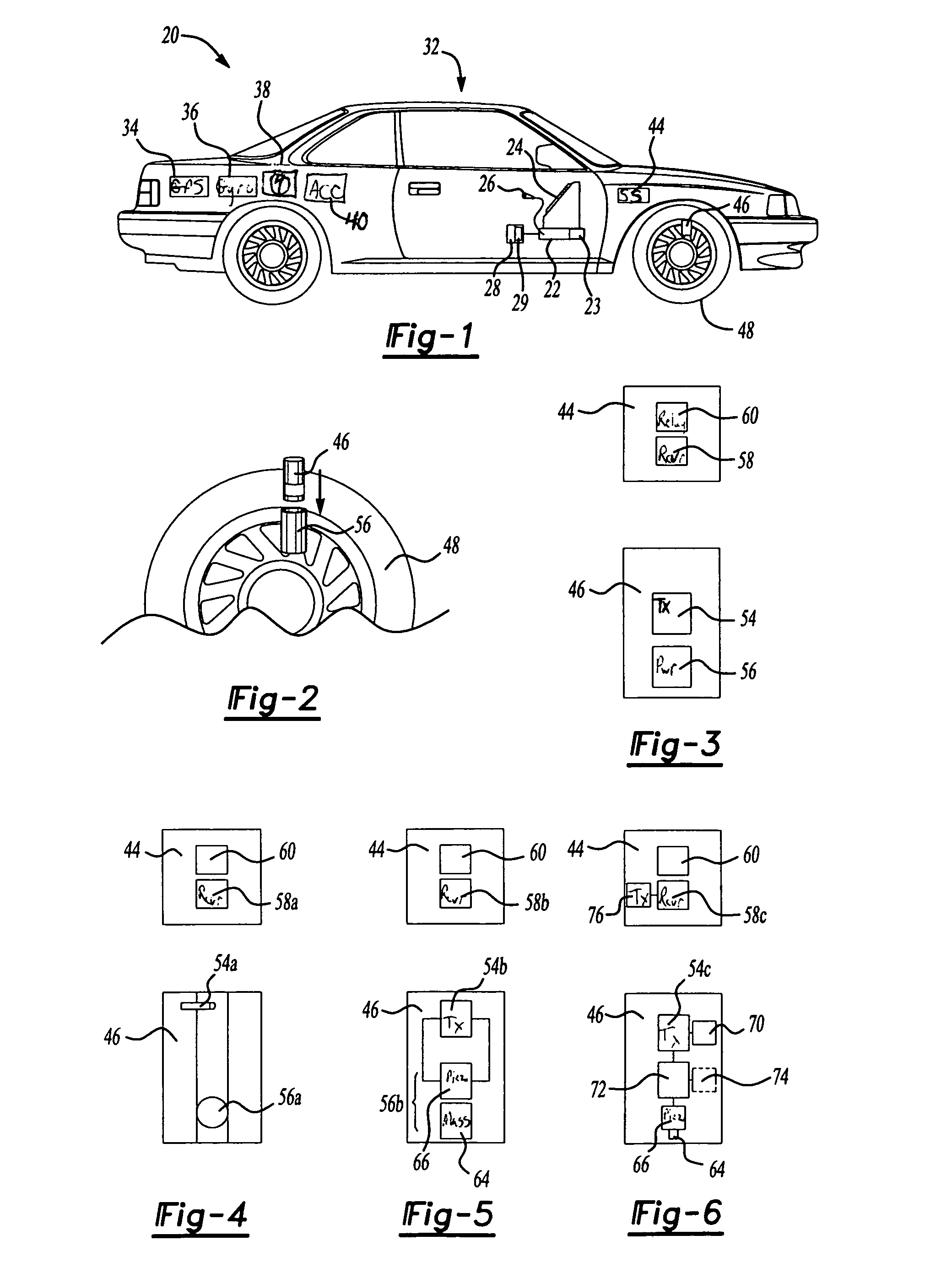
[0024]FIG. 5 illustrates a second embodiment wherein the power source 56b comprises a mass 64 secured to a piezo generator 66. The piezo generator 66 is connected to a resonant LC tank circuit 54b. During each revolution, the mass 64 moves a distance with force and generates electrical charge to cause the resonant LC tank circuit 54b to generate a short RF burst. The receiver 58b is tuned to the frequency of the resonant LC tank circuit 54b. The circuitry 60 sends a signal to the CPU 22 (FIG. 1) each time the RF burst is received from the remote unit 46, indicating one revolution of the wheel 48.

third embodiment

[0025]FIG. 6 illustrates the wheel speed sensor of FIG. 3. The remote unit 46 again includes the piezo generator 66 and mass 64 which senses the revolutions of the wheel 48. The piezo generator 66 is connected to circuitry 72 which detects the change in force that the mass 64 exerts on the piezo generator 66 during revolution from positive 1G to negative 1G. The transmitter 54C is preferably an RF transmitter powered by a battery 70. The transmitter 54C may send an RF burst or “beacon” signal once or twice per revolution of the wheel 48.

[0026]More preferably, the circuitry 72 accumulates a plurality of revolutions, preferably between 10 to 50, and generates a modulated signal which is sent by the RF transmitter 54C. The complementary RF receiver 58C receives the modulated signal indicating a number of revolutions and a circuitry 60 indicates this number to the CPU 22.

[0027]The remote unit 46 optionally includes a receiver 74 which receives an interrogation signal from a transmitter ...


PUM


Abstract

A vehicle navigation system includes a vehicle displacement sensor comprising a wireless transmitter generating a signal indicating rotational displacement of a vehicle component. A complementary wireless transmitter receives the signal from the transmitter. A computer calculates vehicle speed or displacement based upon the rotational speed or displacement of the vehicle component. In a preferred embodiment, the transmitter is secured to a wheel of the vehicle and generates an RF signal upon each revolution of the wheel.

Description

[0001]This application claims priority to U.S. Provisional Application Ser. No. 60 / 120,931 that was filed on Feb. 22, 1999.BACKGROUND OF THE INVENTION[0002]The present invention relates generally to a vehicle speed sensor and more particularly to a vehicle speed sensor for use in a navigation or dead reckoning system.[0003]Many vehicle navigation or route-guidance systems utilize “dead-reckoning” to propagate the position of the vehicle, usually in combination with other sensors and known techniques, such as a GPS receiver, map-matching, etc. For dead-reckoning, generally the displacement or speed of the vehicle is measured, as is the vehicle's heading. By determining the displacement of the vehicle in a determined heading, the position of the vehicle is propagated, typically relative to a database of roads.[0004]The speed and / or displacement of the vehicle is currently obtained directly from the vehicle's electrical and control systems. Since vehicles' electrical control systems ar...

Claims


Application Information

Patent Timeline
Patent Type & Authority Patents(United States)
IPC IPC(8): G08G1/123
CPCG01C22/00G01C21/005
Inventor BEGIN, JOHN D.SPENCER, LARRY
Owner DIDI HK SCI & TECH LTD
Why Eureka
Try Eureka