Method and apparatus for controlling a plurality of image capture devices in a surveillance system

a technology of image capture device and surveillance system, which is applied in the direction of television system, burglar alarm, instruments, etc., can solve the problems of system inefficiency, redundancy of rest of image capture device (and their respective monitors or screens), and difficulty for a single viewer to monitor

Active Publication Date: 2006-07-11
HEWLETT PACKARD DEV CO LP
View PDF9 Cites 67 Cited by
  • Summary
  • Abstract
  • Description
  • Claims
  • Application Information

AI Technical Summary

Benefits of technology

[0016]It will be appreciated that one of the significant advantages of the first aspect of the invention is the ability to provide a single (unitary or distributed) control apparatus to control the operation of a plurality of cameras, as opposed to the cameras each controlling their own operation.
[0017]It will be appreciated that the control apparatus may comprise a central control unit for controlling the operation of all of the image capture devices, or

Problems solved by technology

However, such systems are somewhat inefficient in the sense that many (if not all) of the images captured by the devices will be of little or no interest to the viewer for much of the time as no unauthorised activities will be taking place within their respective fields of view.
In fact, it is most likely that unauthorised activities, if any, will be taking place within the field of view of only a single image capture device at any one time, making the rest of the image capture devices (and their respective monitors or screens) redundant.
Further, it can be quite difficult for a single viewer to monitor the content of images being displayed on several different monitors at the same time, thereby giving rise to the possibility that any unauthorised activities would be missed.
This is obviously undesirable as any unauthorised activities may be taking place within the field of view not currently being displayed on the monitor or screen, again increasing the possibility that such activities will go undetected.
However, the continuous transmission of images captured by a

Method used


Image

  • Method and apparatus for controlling a plurality of image capture devices in a surveillance system
  • Method and apparatus for controlling a plurality of image capture devices in a surveillance system
  • Method and apparatus for controlling a plurality of image capture devices in a surveillance system

Examples


Embodiment Construction

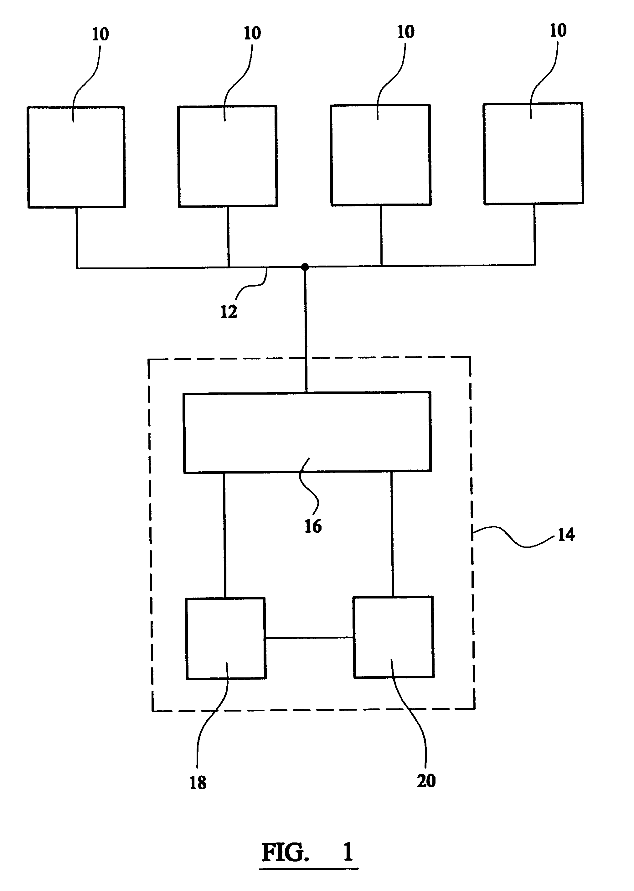
[0023]Referring to FIG. 1 of the drawings, a surveillance system according to an exemplary embodiment of the present invention comprises a plurality of video cameras 10 mounted or otherwise placed in spaced apart relation within an area to be monitored. In a preferred embodiment, the cameras 10 are positioned such that the edges of the fields of view of adjacent cameras are either immediately next to each other (i.e. with little or no gap) or even slightly overlap to prevent “blind spots”.

[0024]The cameras 10 are linked (either by hard wired connections 12 or wireless links) to an ethernet-based control unit 14. The control unit 14 includes an interface 16 for receiving the outputs from the cameras 10 and sending signals to the cameras to alter their operating mode, as necessary.

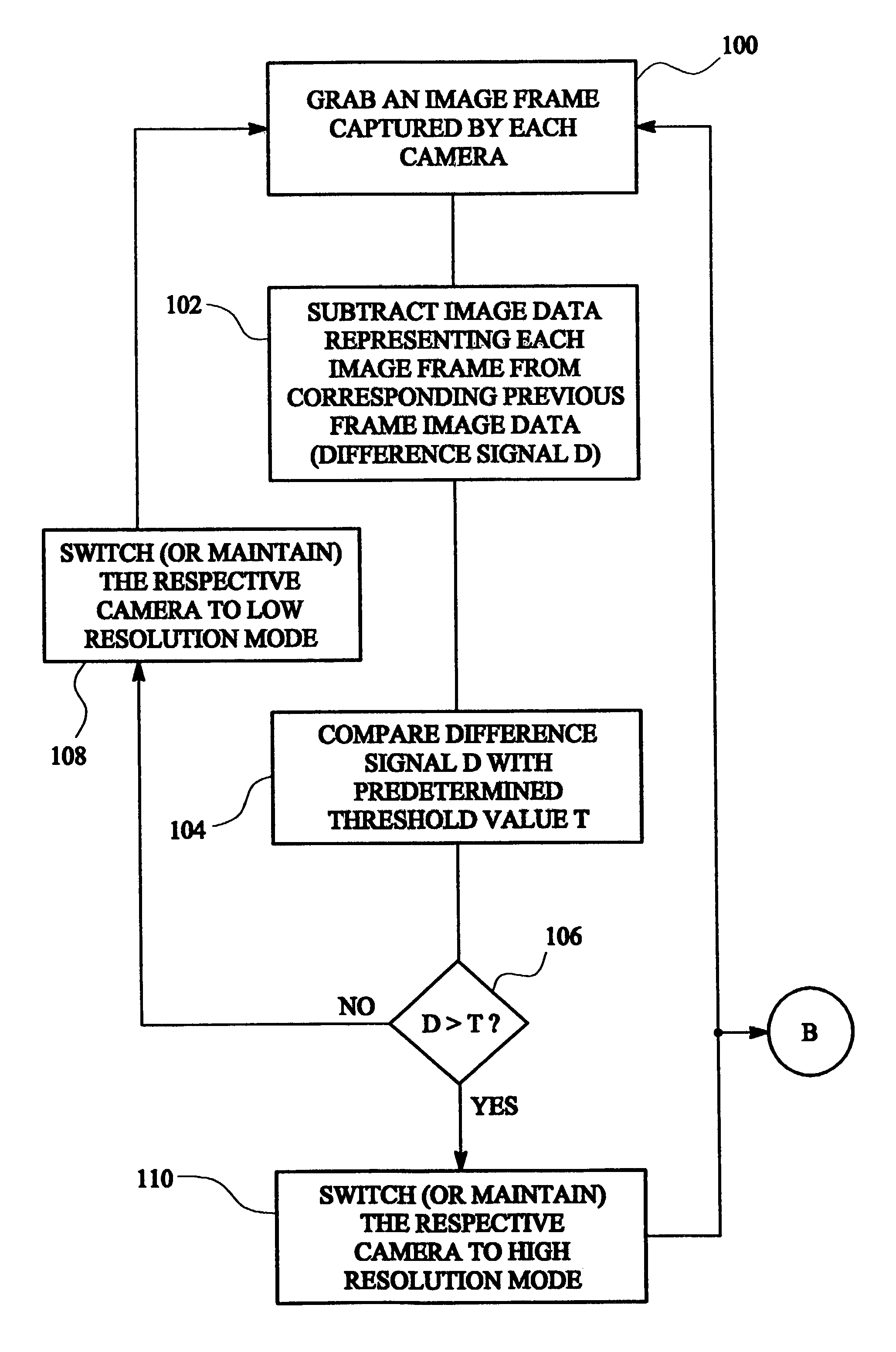
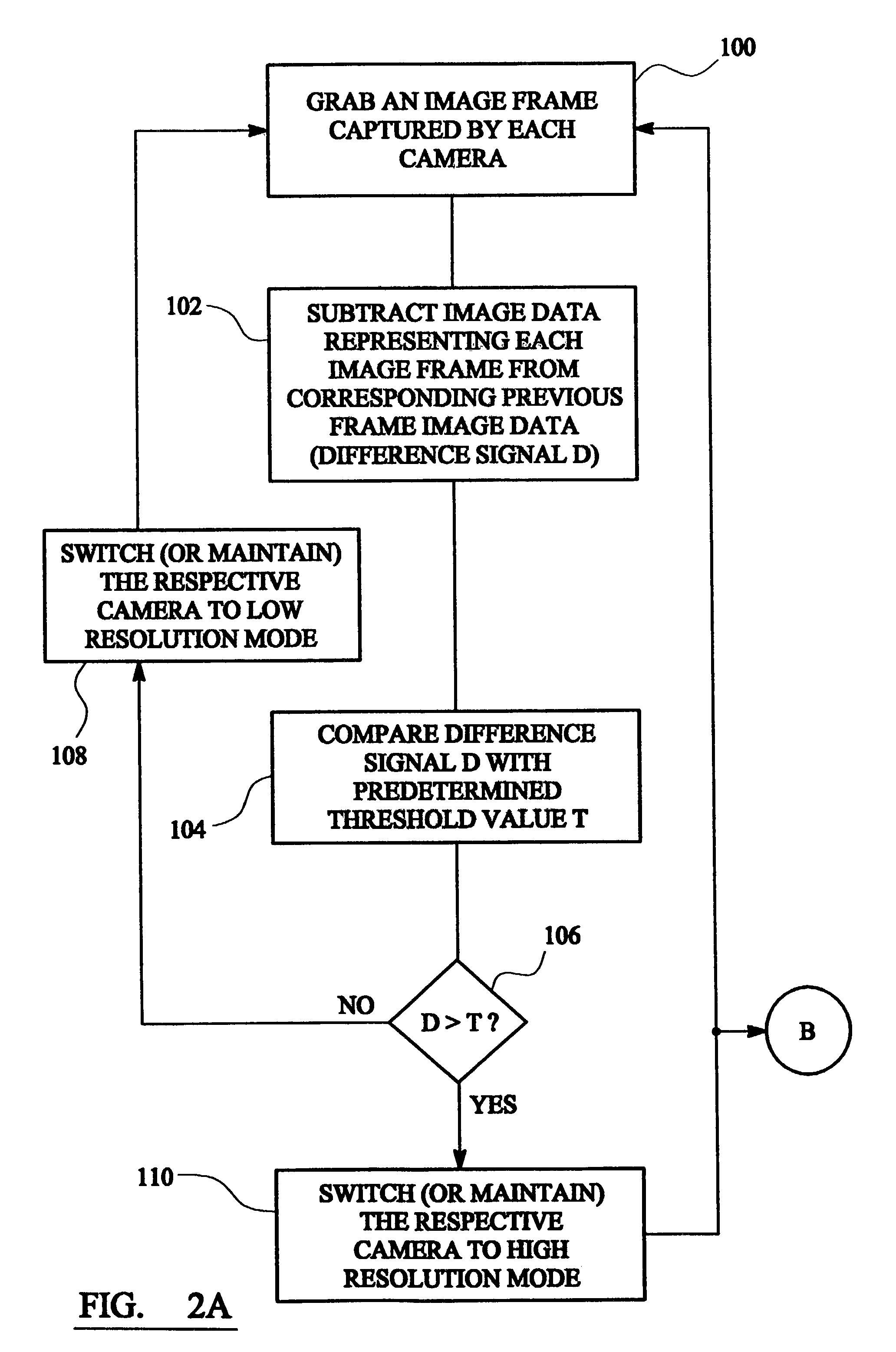
[0025]The control unit 14 further comprises a motion detection apparatus 18 for monitoring the images received from the cameras 10 and detecting motion therein. In one embodiment of the present invention, th...


PUM


Abstract

A method and apparatus for controlling the operation of a system having a plurality of video cameras. The cameras are linked to a control unit which has a motion detection apparatus for monitoring the images received from the cameras and detecting motion therein. The cameras are adapted to operate in at least two modes: a low resolution mode and a high resolution mode. Under normal circumstances, cameras will be operating in low resolution mode to minimize use of system resources. If activity is detected within the field of view of one of the cameras, that camera is switched to high resolution, the other cameras remaining in the low resolution mode.

Description

FIELD OF THE INVENTION[0001]This invention relates to a method and apparatus for controlling multiple image capture devices and, in particular, to a method and apparatus for controlling the status of a plurality of image capture devices in a system, such as a surveillance system or the like.BACKGROUND OF THE INVENTION[0002]It is well known to provide within a building or similar enclosure a plurality of image capture devices mounted or otherwise placed at various key locations so as to provide a surveillance system for monitoring and / or capturing unauthorised activities within the building or enclosure.[0003]In its simplest form, such a surveillance system comprises a plurality of image capture devices, such as cameras for capturing still or (more commonly) moving images, each of which is linked or connected to a respective display screen or monitor on which the images captured by the devices can be viewed. Thus, a typical system would have a plurality of monitors located at a centr...

Claims


Application Information

Patent Timeline
IPC IPC(8): H04N5/228G08B13/196H04N7/18H04N7/26H04N7/46
CPCG08B13/19608G08B13/19641G08B13/19667H04N19/587H04N19/103H04N19/137H04N7/181
Inventor HUNTER, ANDREW ARTHURCHEATLE, STEPHEN PHILIP
Owner HEWLETT PACKARD DEV CO LP
Why Eureka
Try Eureka