Systems and methods for interference-suppression with directional sensing patterns

a technology of directional sensing pattern and interference suppression, applied in the direction of electrical transducers, electrical transducers, transducer types, etc., can solve the problems of difficult extraction of desired signals in the presence of interfering signals, devices that do not permit selective amplification of desired sounds, and even more severe problems, so as to reduce the variance of output signals

Inactive Publication Date: 2006-07-11
THE BOARD OF TRUSTEES OF THE UNIV OF ILLINOIS
View PDF118 Cites 29 Cited by
  • Summary
  • Abstract
  • Description
  • Claims
  • Application Information

AI Technical Summary

Benefits of technology

[0009]Yet another embodiment includes a number of sensors oriented in relation to a reference axis and operable to provide a number of sensor signals representative of sound. The sensors each have a directional response pattern with a maximum response direction, and are arranged in a predefined positional relationship relative to one another with a separation distance of less than two centimeters to reduce a difference in time of reception between the sensors for sound emanating from a source closer to one of the sensors than another of the sensors. The processor generates an output signal from the sensor signals as a function of a number of signal weights for each of a number of different frequencies. The signal weights are adaptively recalculated from time-to-time.
[0010]Still a further embodiment of the present invention includes: positioning a number of directional sensors in a predefined geometry relative to one another that each have a directional pattern with sound response being attenuated by at least 3 decibels from one direction relative to another direction at a selected frequency; detecting acoustic excitation with the sensors to provide a corresponding number of sensor signals; establishing a number of frequency domain components for each of the sensor signals; and determining an output signal representative of the acoustic excitation from a designated direction. This determination can include weighting the components for each of the sensor signals to reduce variance of the output signals and provide a predefined gain of the acoustic excitation from the designated direction.

Problems solved by technology

The difficulty of extracting a desired signal in the presence of interfering signals is a long-standing problem confronted by engineers.
This problem impacts the design and construction of many kinds of devices such as acoustic-based systems for interrogation, detection, speech recognition, hearing assistance or enhancement, and / or intelligence gathering.
Generally, such devices do not permit the selective amplification of a desired sound when contaminated by noise from a nearby source.
This problem is even more severe when the desired sound is a speech signal and the nearby noise is also a speech signal produced by other talkers.

Method used


Image

  • Systems and methods for interference-suppression with directional sensing patterns
  • Systems and methods for interference-suppression with directional sensing patterns
  • Systems and methods for interference-suppression with directional sensing patterns

Examples


Embodiment Construction

[0024]While the present invention can take many different forms, for the purpose of promoting an understanding of the principles of the invention, reference will now be made to the embodiments illustrated in the drawings and specific language will be used to describe the same. It will nevertheless be understood that no limitation of the scope of the invention is thereby intended. Any alterations and further modifications of the described embodiments, and any further applications of the principles of the invention as described herein are contemplated as would normally occur to one skilled in the art to which the invention relates.

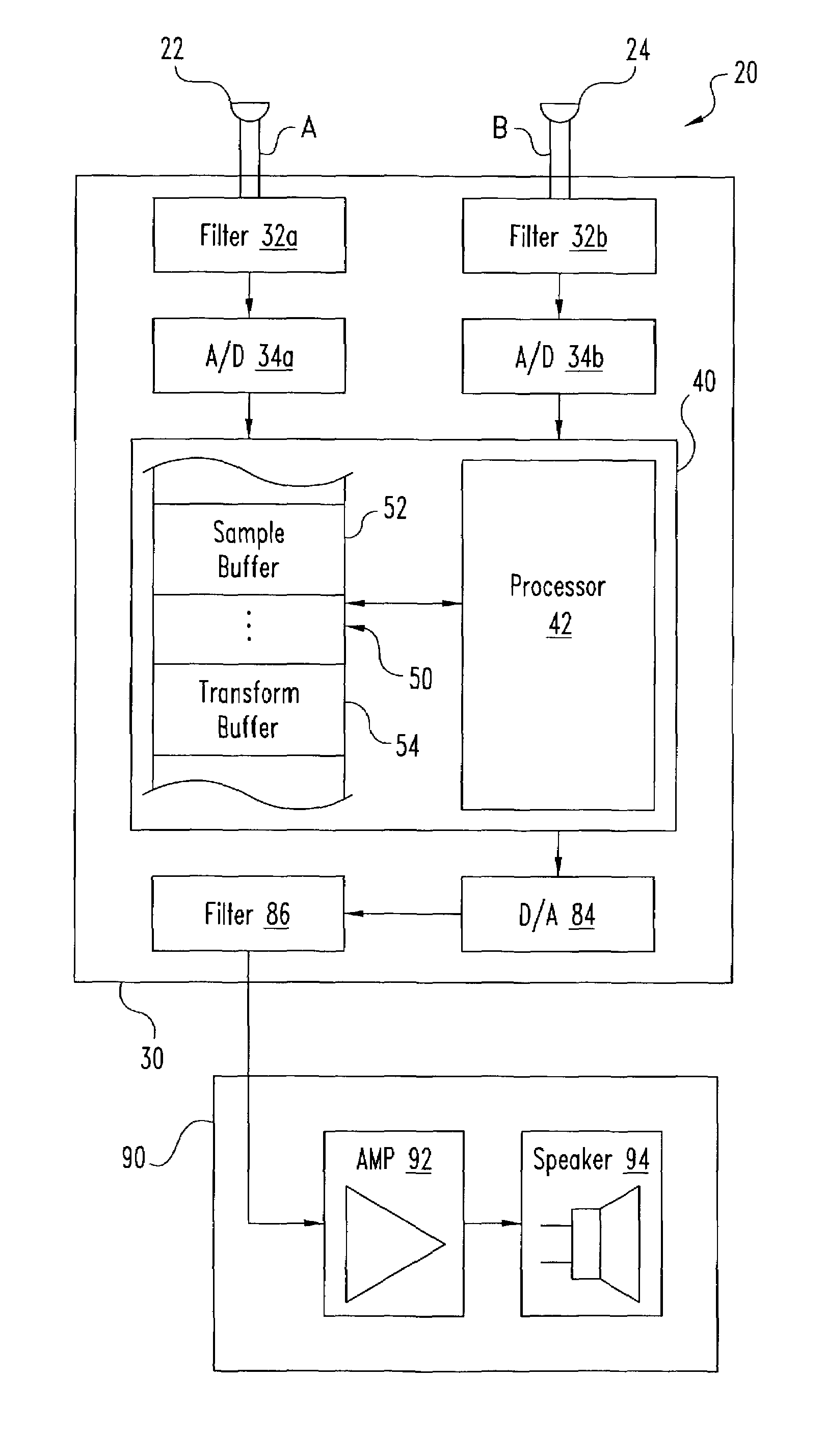
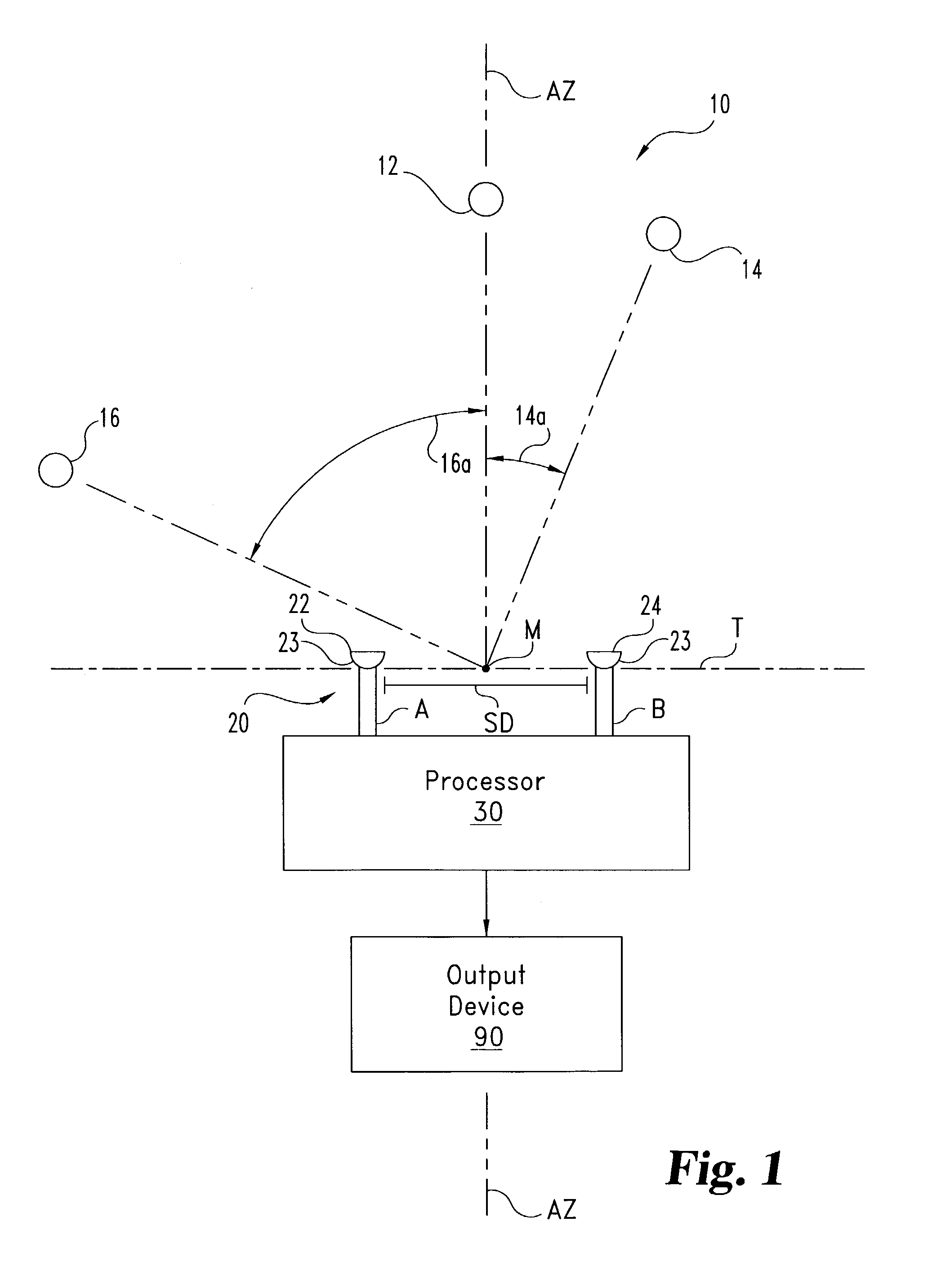
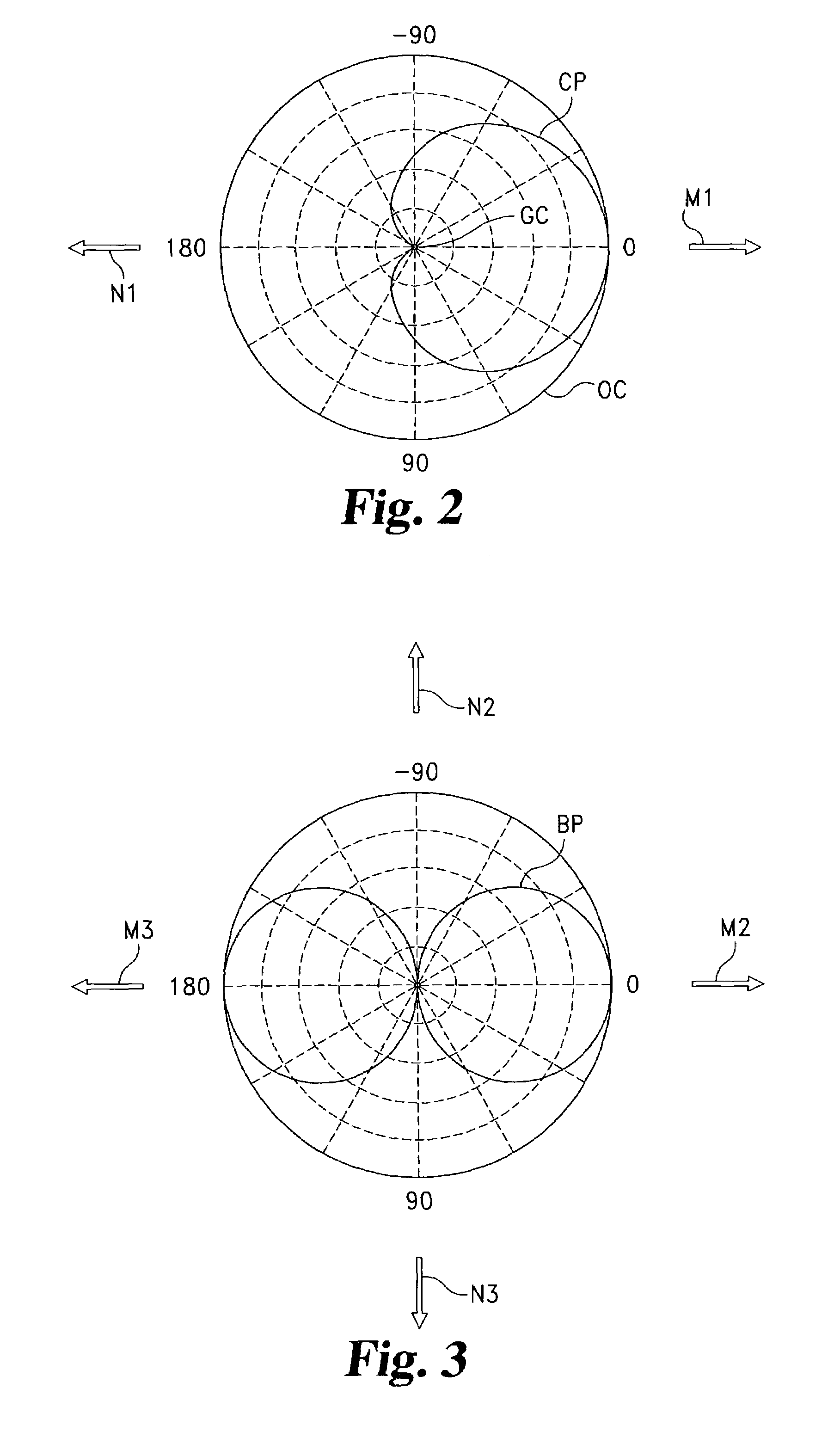
[0025]FIG. 1 illustrates an acoustic signal processing system 10 of one embodiment of the present invention. System 10 is configured to extract a desired acoustic excitation from acoustic source 12 in the presence of interference or noise from other sources, such as acoustic sources 14, 16. System 10 includes acoustic sensor array 20. For the example illustr...


PUM


Abstract

System (10) is disclosed including an acoustic sensor array (20) coupled to processor (42). System (10) processes inputs from array (20) to extract a desired acoustic signal through the suppression of interfering signals. The extraction / suppression is performed by modifying the array (20) inputs in the frequency domain with weights selected to minimize variance of the resulting output signal while maintaining unity gain of signals received in the direction of the desired acoustic signal. System (10) may be utilized in hearing, cochlear implants, speech recognition, voice input devices, surveillance devices, hands-free telephony devices, remote telepresence or teleconferencing, wireless acoustic sensor arrays, and other applications.

Description

GOVERNMENT RIGHTS[0001]This invention was made with Government support under Contract Number 240-67628 awarded by DARPA. The Government has certain rights in the invention.CROSS-REFERENCE TO RELATED APPLICATIONS[0002]The present application is related to International Patent Application Number PCT / US01 / 15047 filed on May 10, 2001; International Patent Application Number PCT / US01 / 14945 filed on May 9, 2001; U.S. patent application Ser. No. 09 / 805,233 filed on Mar. 13, 2001; U.S. patent application Ser. No. 09 / 568,435 filed on May 10, 2000; U.S. patent application Ser. No. 09 / 568,430 filed on May 10, 2000; International Patent Application Number PCT / US99 / 26965 filed on Nov. 16, 1999; and U.S. Pat. No. 6,222,927 B1; all of which are hereby incorporated by reference.[0003]The present invention is directed to the processing of signals, and more particularly, but not exclusively, relates to techniques to extract a signal from a selected source while suppressing interference from one or mo...

Claims


Application Information

Patent Timeline
Patent Type & Authority Patents(United States)
IPC IPC(8): H04R25/00H04R11/04H04R3/00H04R1/40
CPCH04R1/406H04R25/407H04R3/005H04R2410/01
Inventor FENG, ALBERT S.LOCKWOOD, MICHAEL E.JONES, DOUGLAS L.BILGER, LEGAL REPRESENTATIVE, CAROLYN J.LANSING, CHARISSA R.O'BRIEN, WILLIAM D.WHEELER, BRUCE C.BILGER, DECEASED, ROBERT C.
Owner THE BOARD OF TRUSTEES OF THE UNIV OF ILLINOIS
Why Eureka
Try Eureka