
Weather prediction system and power demand prediction system, and weather prediction method and power demand prediction method

a prediction system and weather technology, applied in the field of weather prediction system and power demand prediction system, can solve the problems of increasing power consumption of air conditioners, difficult to predict flood risk, and no attempt to estimate the latter artificial exhaust heat and refl

Inactive Publication Date: 2006-07-11
KK TOSHIBA
View PDF2 Cites 8 Cited by
  • Summary
  • Abstract
  • Description
  • Claims
  • Application Information

AI Technical Summary

Benefits of technology

The present invention provides an accurate weather prediction system and power demand prediction system that organically combine weather prediction and power demand prediction while considering artificial heat exhaust. The system predicts meteorological phenomena and power demand in each region by inputting prediction information and observation information of meteorological factors to a local numerical weather prediction model of the specific region. The generated heat value predicted for each region is reflected on the numerical weather prediction model. The technical effects of the invention include improved accuracy in predicting weather and power demand, and improved decision-making for energy management.

Problems solved by technology

However, no attempt has been made to estimate the latter artificial exhaust heat and reflect it on prediction of meteorological phenomena.
That is, when the temperature rises, the power consumption by air conditioners increases.
Hence, the underestimation adversely affects prediction of local severe rain and makes it difficult to predict flood risk.
It may also lead to degradation in prediction accuracy of the power demand which is calculated on the basis of meteorological phenomena.

Method used


Image

  • Weather prediction system and power demand prediction system, and weather prediction method and power demand prediction method
  • Weather prediction system and power demand prediction system, and weather prediction method and power demand prediction method
  • Weather prediction system and power demand prediction system, and weather prediction method and power demand prediction method

Examples


Embodiment Construction

[0017]The embodiment of the present invention will be described below in detail with reference to the accompanying drawing.

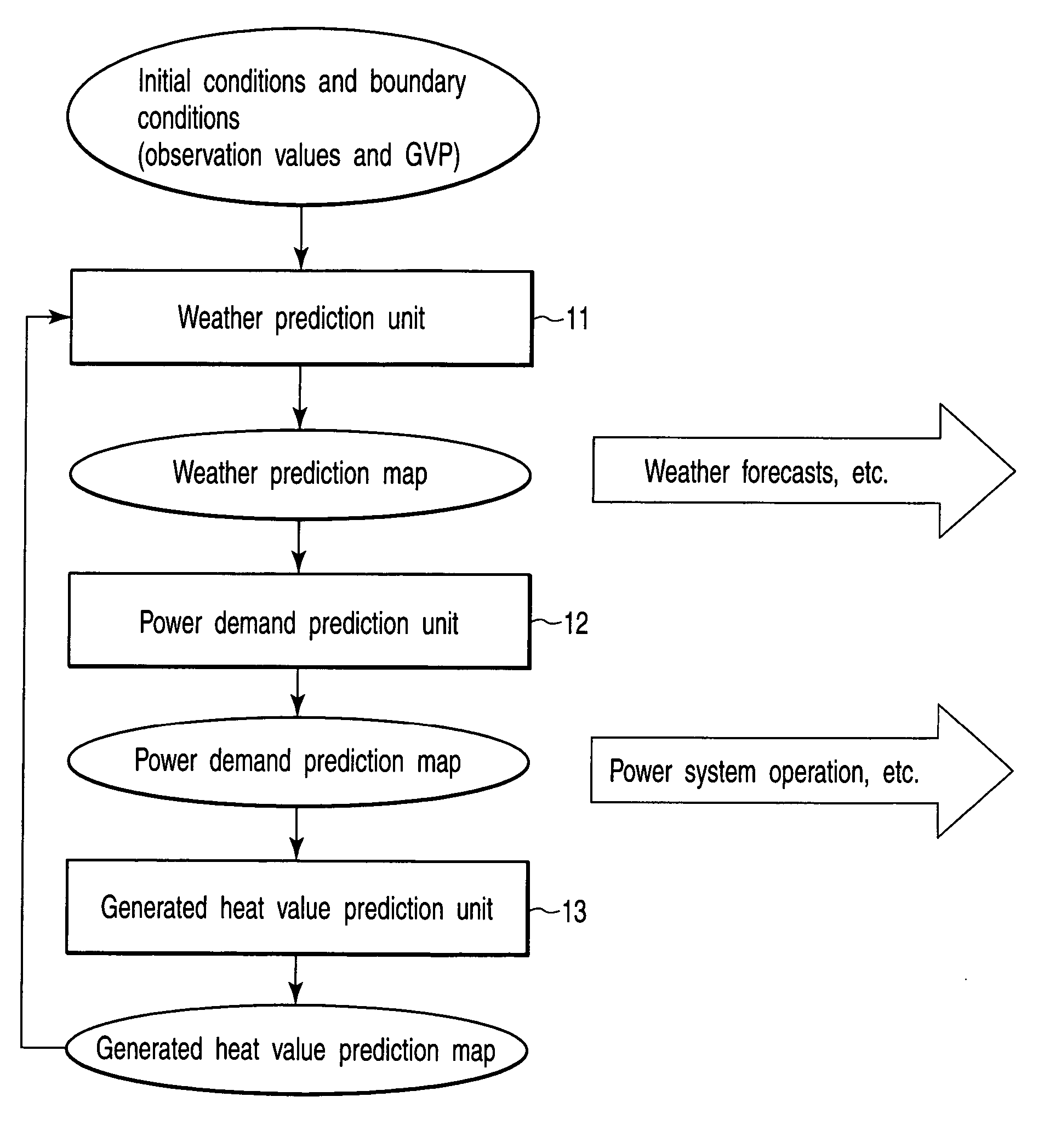
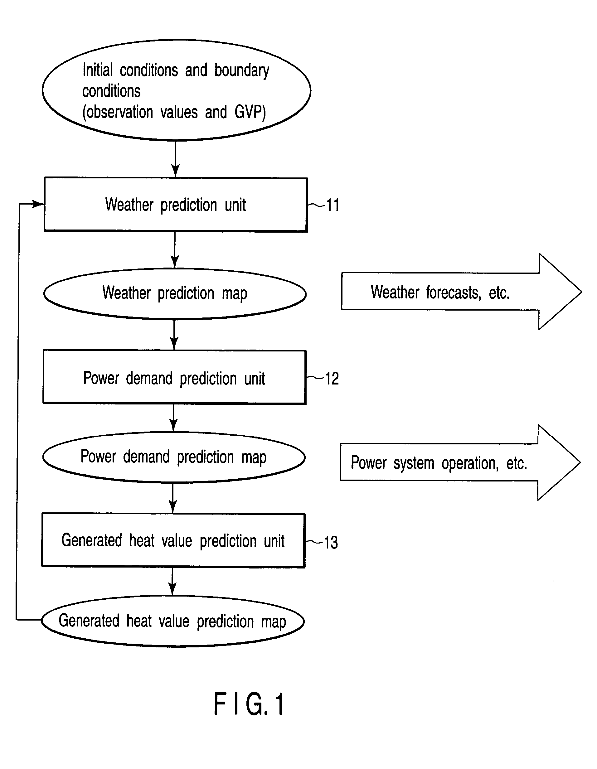
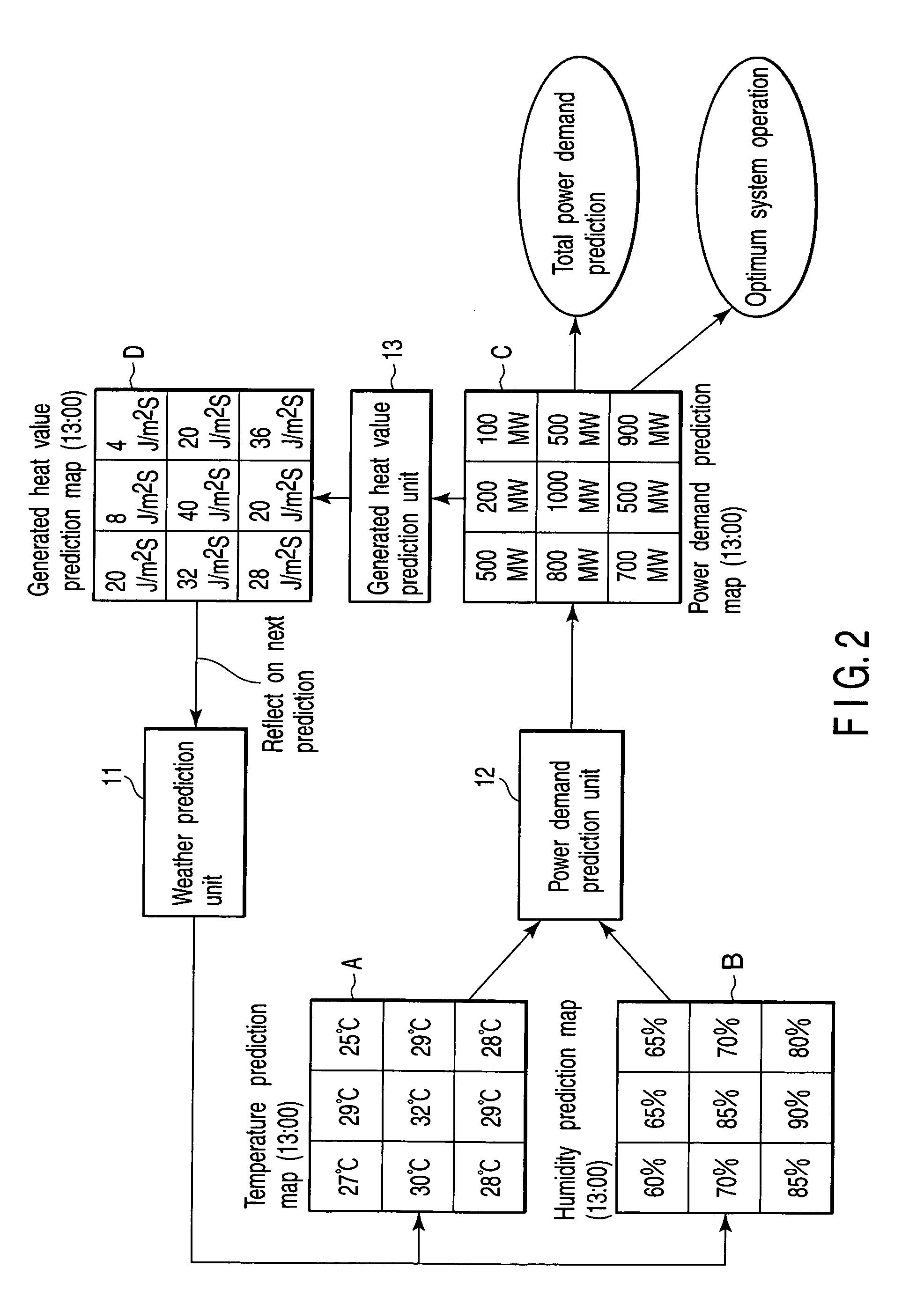
[0018]FIG. 1 is a block diagram showing a system configuration of the present invention. This system includes a weather prediction unit 11, power demand prediction unit 12, and generated heat value prediction unit 13. FIG. 2 shows examples of prediction maps (prediction time 13:00) generated by the prediction units 11 to 13.

[0019]The weather prediction unit 11 receives external meteorological information (i.e., initial conditions and boundary conditions) from meteorological agencies and similar agencies of the world. Each agency or organization provides the information. The external meteorological information consists of data items representing the meteorological factors predicted at grid points. The set of these data items is called GPV (Grid Point Value) data. The GPV data is produced based on GSM (Global Spectrum Model), RSM (Regional Spectrum Model), MSM (Me...


PUM


Abstract

A weather prediction unit calculates a local numerical weather prediction model from GPV data and weather observation data and predicts a regional meteorological phenomenon in a fractionated region. A power demand prediction unit predicts a power demand in each region on the basis of the regional prediction result of the meteorological phenomenon. A generated heat value prediction unit predicts a generated heat value in each region on the basis of the regional prediction result of the power demand. The regional prediction result of the generated heat value is reflected on the numerical weather prediction model. Meteorological phenomena are predicted by adding the thermal energy as sensible heat from the earth's surface and taking artificial exhaust heat by electrical energy into consideration. Accordingly, weather prediction and power demand prediction are organically combined so that accurate weather prediction and power demand prediction are implemented while considering artificial heat exhaust.

Description

CROSS-REFERENCE TO RELATED APPLICATIONS[0001]This application is based upon and claims the benefit of priority from prior Japanese Patent Application No. 2003-370843, filed Oct. 30, 2003, the entire contents of which are incorporated herein by reference.BACKGROUND OF THE INVENTION[0002]1. Field of the Invention[0003]The present invention relates to a weather prediction system and power demand prediction system, and a weather prediction method and power demand prediction method which predict a meteorological phenomenon and a power demand on the basis of the relationship between meteorological phenomena and power demands.[0004]2. Description of the Related Art[0005]Conventionally, prediction of meteorological phenomena is done independently of prediction of power demands. In recent years, atmospheric simulation software called a numerical weather prediction model. By using this software, meteorological phenomena are predicted several hours to about one week in the future. On the other...

Claims


Application Information

Patent Timeline
Patent Type & Authority Patents(United States)
IPC IPC(8): G01W1/00G01W1/10G06Q50/00G06Q50/06H02J3/00
CPCG01W1/10
Inventor WADA, MASAKAZU
Owner KK TOSHIBA
Learn More