Filtering method and apparatus

a filtering method and filtering technology, applied in the field of filtering methods and apparatuses, can solve the problems of increasing the computational complexity of the hybrid filter bank, and achieving the effect of reducing the cost of decoding, increasing the computational complexity and increasing the cost of the entire decoder

Inactive Publication Date: 2006-07-11
SEIKO EPSON CORP
View PDF9 Cites 5 Cited by
  • Summary
  • Abstract
  • Description
  • Claims
  • Application Information

AI Technical Summary

Benefits of technology

[0050]However, in the conventional decoder, the percentage of the computational complexity of the hybrid filter bank to the computational complexity of the entire decoder reaches about 70 percent. Namely, in the decoder, the percentage of the computational complexity is greater in the sub-band synthesis processing and the inverse MDCT processing or the like as shown in FIGS. 11, 12 and 14. In such processing, the sub-band synthesis buffer 263a needs the amount of data of 64×16=1024 blocks, and the inverse MDCT buffer needs the amount of data of 18×32=576 blocks, causing the cost of the entire decoder to be increased.
[0051]It is an object of the present invention to provide a filtering method and apparatus in which the number of arithmetical operations required in the filtering process in decoding the digital signal and the cost of decoding is reduced.
[0076]In each of these aspects, in decoding the digital signal from the frequency domain to the time domain, the number of arithmetical operations performed in the filtering and the memory capacity of data required for the operation can be reduced. Therefore, the decoding can be performed more rapidly, and the cost required for decoding reduced. Further, the power consumption required for the decoding process can be saved.
[0078]Also, even when the coded data through various windows is mingled in the input data stream, a decoding process can be appropriately performed.

Problems solved by technology

However, in the conventional decoder, the percentage of the computational complexity of the hybrid filter bank to the computational complexity of the entire decoder reaches about 70 percent.
In such processing, the sub-band synthesis buffer 263a needs the amount of data of 64×16=1024 blocks, and the inverse MDCT buffer needs the amount of data of 18×32=576 blocks, causing the cost of the entire decoder to be increased.

Method used


Image

  • Filtering method and apparatus
  • Filtering method and apparatus
  • Filtering method and apparatus

Examples


Embodiment Construction

[0094]The preferred embodiments of a hybrid filter bank 10 according to the present invention will be described below with reference to the drawings.

[0095]FIGS. 1 to 8 are diagrams showing the hybrid filter bank (hereinafter referred to as an “HFB”) 10 to which the invention is applied.

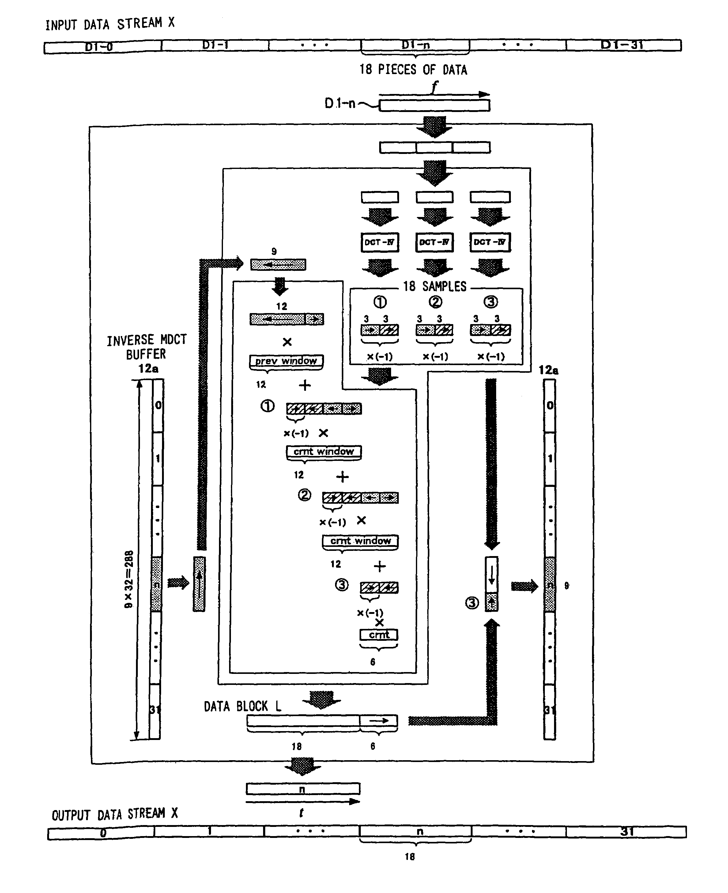
[0096]The hybrid filter bank 10 according to the invention is provided in a digital signal decoder such as an MP3 decoder, to transform a signal from the frequency domain to the time domain.

[0097]Firstly, the configuration of the hybrid filter bank 10 will be set forth.

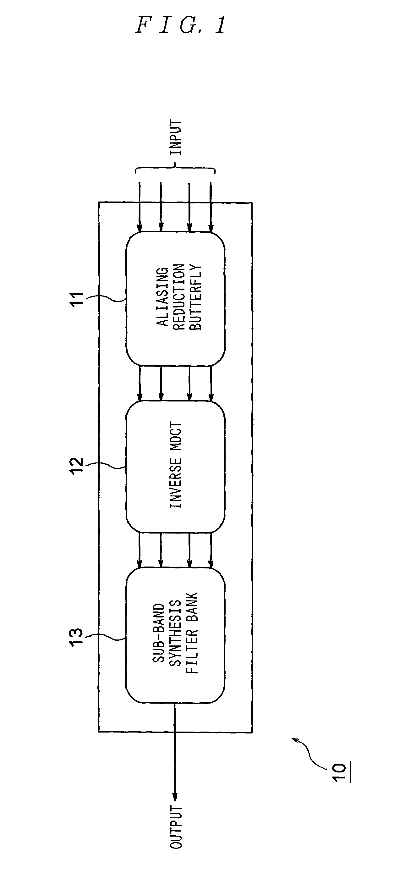
[0098]FIG. 1 is a diagram showing the configuration of the hybrid filter bank 10 to which the invention is applied.

[0099]In FIG. 1, the HFB 10 comprises an alias reduction butterfly 11, an inverse MDCT 12, and a sub-band synthesis filter bank 13. The configuration of the alias reduction butterfly 11 is the same as that of the conventional HFB 260, and the explanation thereof is omitted here.

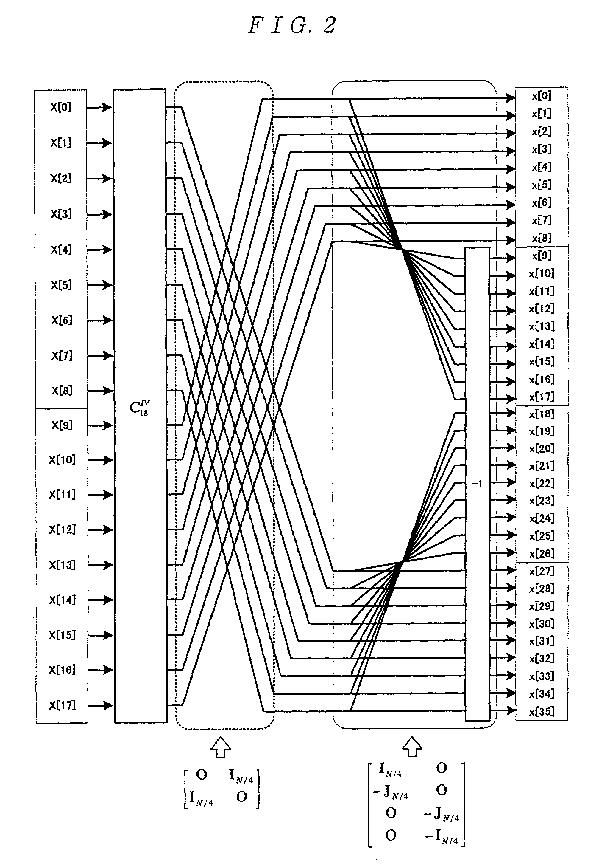
[0100]The inverse MDCT 12 comprises an inverse...


PUM


Abstract

To decrease the number of arithmetical operations in a filtering process for decoding a digital signal and reduce a cost required for decoding. A filtering method for use in decoding a digital signal from a frequency domain to a time domain includes: a first step of multiplying an input data stream and a transformation matrix that is decomposed into a sparse matrix from an inverse MDCT transformation matrix for making the inverse MDCT transformation of the input data stream composed of a plurality of data blocks, and has a smaller size than the inverse MDCT transformation matrix, to acquire an output data stream composed of a plurality of data blocks; a second step of storing predetermined data contained in each data block of the output data stream; and a third step of generating the digital signal in the time domain on the basis of each data block acquired at the first step and the predetermined data stored at the second step in processing the former stage data block.

Description

BACKGROUND OF THE INVENTION[0001]1. Field of the Invention[0002]The present invention relates to a filtering method and apparatus for use in decoding the digital signal from the frequency domain to the time domain.[0003]2. Description of the Prior Art[0004]Conventionally, a method for decoding the digital signal in the MP3 (MPEG Audio Layer III) or the like from the frequency domain to the time domain was well known that employed the filtering with a hybrid filter bank.[0005]FIG. 9 is a diagram showing the configuration of functions of an encoder 100 and a decoder 200 in accordance with the MP3 standards. The main functions of the encoder 100 and the decoder 200 will be set forth below with reference to FIG. 9.[0006]In FIG. 9, the encoder 100 comprises a hybrid filter bank (hereinafter referred to as an “HFB”) 110, a psychoacoustic analysis portion 120, an iteration loop 130, a Huffman coding portion 140, a side information coding portion 150, and a stream composing portion 160.[000...

Claims


Application Information

Patent Timeline
Patent Type & Authority Patents(United States)
IPC IPC(8): G06F17/14H03H17/02
CPCG06F17/147
Inventor TODOROKI, AKINARIBAISHO, FUMIHITO
Owner SEIKO EPSON CORP
Why Eureka
Try Eureka