Pressurizing method

a pressurizing apparatus and pressurizing technology, applied in the direction of chemistry apparatus and processes, instruments, manufacturing tools, etc., can solve the problems of affecting the application of the acf layer, affecting the quality of the plate, so as to prevent static damage to the object to be joined, reduce the amount of waste on the plate, and increase the jointing strength between the bonding layer and the plate-like component.

Inactive Publication Date: 2006-07-18
PANASONIC CORP
View PDF15 Cites 5 Cited by
  • Summary
  • Abstract
  • Description
  • Claims
  • Application Information

AI Technical Summary

Benefits of technology

[0025]It is preferable that a portion of the bonding layer of the bonding sheet adhering to an object by virtue of the joining force of the bonding layer is cooled by spraying gas. By cooling the bonding layer of the bonding sheet, a joining strength between the bonding layer and the plate-like component increases. For this reason, at a time when the base layer is stripped from the plate-like component, a problem of resulting in partial or entire stripping of the bonding layer from the object, because a joining force between the bonding layer and the plate-like component becomes lower than a joining force between the base layer and the bonding layer, can be prevented.
[0026]The above-mentioned cooling may be performed by spraying gas. In this case, ions may be included in the gas. In a case where the ions are included, static electricity is eliminated, by action of the ions, from the object to be joined, whereby static damage to the object to be joined can be prevented.
[0027]In a case where the plate-like component is equipped with conductors and an electrode section formed on first ends of the conductors, and when a bonding sheet is pressurized against the electrode section, it is preferable that gas is sprayed to the plate-like component in a direction from other ends of the conductors to the first ends thereof. In a case where the plate-like component is an LCD board, for example, it is preferable that gas is sprayed from ends of driver voltage supply lines, on a side of an LCD section, to ends thereof on a side of the electrode section. In this case, waste on the plate-like component can be eliminated by blowing it off by using sprayed gas. The waste of this kind is waste generated from the ACF tape, glass chips generated from the LCD board, and the like.
[0028]Instead of gas, a refrigerant may be supplied to the tool to cool the bonding sheet via the tool. It is preferable that heating of the tool is stopped when the refrigerant is supplied, in particular. In this case, a cooling efficiency of the tool by using the refrigerant is improved, whereby a cooling speed of the bonding layer can be increased.
[0029]Gas may be sprayed toward the slit of the bonding sheet to perform cooling. Since the slit corresponds to the fringe of the tool, a pressurizing force applied by the tool may become non-uniform, whereby sufficient joining strength may not be obtained between the bonding layer and the plate-like component. Hence, when the base layer is stripped, the bonding layer is apt to be stripped from the plate-like component or the bonding layer is apt to be torn at a portion of the slit, because a joining force between the bonding layer and the plate-like component becomes lower than a joining force between the base layer and the bonding layer. However, by cooling the portion of the slit of the bonding sheet by spraying gas, the joining force between the bonding layer and the plate-like component is improved, whereby stripping or tearing of the bonding layer at the portion of the slit can be prevented.
[0030]In addition, high tension is applied to the bonding sheet when pressurizing and heating are performed by the tool. Hence, if a temperature of the portion in the vicinity of the slit rises excessively, the bonding sheet becomes longer, whereby a position of the slit changes. Owing to the change in the position of the slit, a position of a front end of the bonding layer changes at a time of a next application thereof. Hence, the bonding layer cannot be applied to a predetermined accurate position with respect to a plate-like component. However, by performing cooling by spraying gas to the portion of the slit of the bonding sheet, a temperature of the portion is prevented from rising excessively. As a result, a change in the position of the slit owing to elongation of the bonding sheet is prevented, whereby the bonding layer can be applied to a predetermined accurate position with respect to the plate-like component.

Problems solved by technology

This dust also impairs appropriate application of the ACF layer 5b.
Tool exchange required in a case of stripping of the cover layer and adhesion of dust may cause some problems.
This adjustment is complicated and takes a long time.
This exchange work is complicated.
Just as in the case of the ACF applying apparatus, even in the case of the final-press bonding apparatus, final-press bonding of the film-like components to plate-like components is repeated, whereby stripping of the cover layer from the tool and adhesion of dust to the tool are caused, resuming in impairing accurate fixing of the film-like components with respect to the plate-like components.
A second problem relates to a temperature of the ACF layer 5b.

Method used


Image

  • Pressurizing method
  • Pressurizing method
  • Pressurizing method

Examples


first embodiment

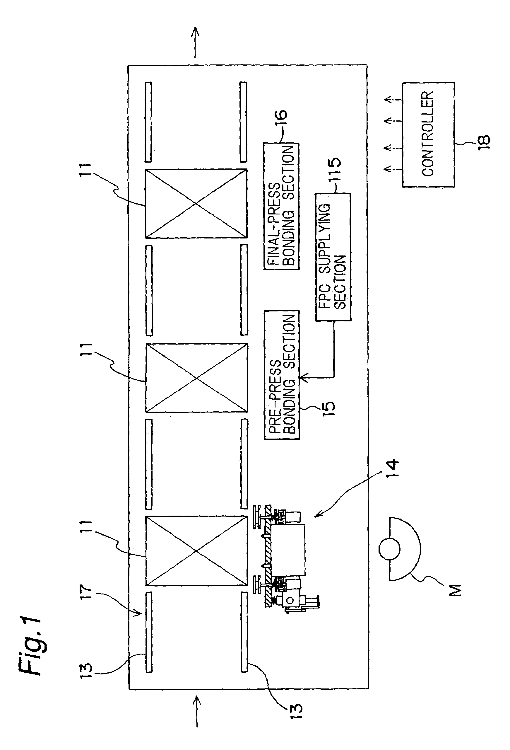
[0076]Next, embodiments in accordance with the present invention will be described referring to the accompanying drawings. FIG. 1 is a component mounting apparatus in accordance with an embodiment of the present invention. As shown in FIG. 32, this component mounting apparatus is intended to mount flexible printed circuit boards (FPC boards) 12 on a plasma display panel board (PDP board) 11, driver circuits of which are formed in the FPC boards. The component mounting apparatus comprises a transfer apparatus 17 for transferring the PDP board 11 to an ACF applying apparatus 14, a pre-press bonding apparatus 15 and a final-press bonding apparatus 16 in this order along a pair of guide rails 132. Among the ACF applying apparatus 14, the pre-press bonding apparatus 15 and the final-press bonding apparatus 16, the ACF applying apparatus 14 and the final-press bonding apparatus 16 are apparatuses to which the present invention is applied. A controller 18 controls operations of the ACF app...

second embodiment

[0130]FIGS. 18 to 21 show an ACF applying apparatus in accordance with a second embodiment of the present invention.

[0131]This ACF applying apparatus comprises a stage 19, an ACF tape supplying section 23, a tool 21, a stripping section 124, a cutting section 126 and an ACF tape cooling section 127. This ACF applying apparatus is used to apply ACF tape 5 to an LCD board 129 (object) in this embodiment.

[0132]As shown in FIG. 34, the LCD board 129 comprises a liquid crystal display section 129a and an electrode section 129c, wherein ends of a plurality of driver voltage supply lines 129b are disposed linearly. ACF layer 5b of ACF tape 5 is applied to this electrode section 129c, and an FPC board 131 is joined by this ACF layer 5b having been applied. The FPC board 131 comprises a driver circuit 131a formed of IC chips and the like, and an electrode section 131c, wherein the driver voltage supply lines 131b of the driver circuit 131a are disposed linearly. At this electrode section 131...

third embodiment

[0161]A mechanism of ACF tape cooling section 127 of a bonding sheet applying section in accordance with a third embodiment of the present invention shown in FIGS. 25 and 26 is different from that of the second embodiment. In other words, the ACF tape cooling section 127 comprises refrigerant passages 130a and 130b provided in a holding member 130, and a refrigerant supplying section 164 for supplying a refrigerant to the refrigerant passages 130a and 130b. The refrigerant passages 130a and 130b are provided so as to pass through the holding member 130 in parallel with heater 131. In addition, one end of the refrigerant passage 130a is connected to one end of the refrigerant passage 130b via a pipe 166a. Furthermore, other ends of the refrigerant passages 130a and 130b are connected to the refrigerant supplying section 164 via separate pipes 166b and 166c, respectively. One of the pipes, i.e., the pipe 166b, is provided with a valve 167 for controlling supply and shutoff of the refr...


PUM

PropertyMeasurementUnit
temperatureaaaaaaaaaa
stress concentrationaaaaaaaaaa

Abstract

A pressurizing method for pressurizing a second component arranged on a first component, against the first component by using a pressurizing apparatus having a stage on which the first component is mounted, a tool, and a protection sheet supplying section. The tool is disposed so as to face the stage and moved between a first position at which the tool faces the first and second components while spaced therefrom, and a second position at which the tool is biased toward the stage to pressurize the second component against the first component. When the tool is at the second position, the protection sheet supplying section supplies a protection sheet so that the protection sheet is placed between the second component and the tool.

Description

BACKGROUND OF THE INVENTION[0001]The present invention relates to a pressurizing apparatus and a pressurizing method for pressurizing bonding sheets including anisotropic conductive film tape (ACF tape), film-like components including flexible printed circuit boards (FPC boards), electronic components, optical components, and the like against a first component, such as a plasma display panel board (PDP board) or a liquid crystal display board (LCD board). The pressurizing apparatus comprises a bonding tape applying apparatus, such as an anisotropic conductive film applying apparatus (ACF applying apparatus), and a final-press bonding apparatus.[0002]A component mounting apparatus for mounting film-like components, such as FPC boards, onto a plate-like component, such as a PDP board or an LCD board, comprises an ACF applying apparatus, a pre-press bonding apparatus and a final-press bonding apparatus. In the ACF applying apparatus, an anisotropic conductive film layer (ACF layer) of ...

Claims


Application Information

Patent Timeline
Patent Type & Authority Patents(United States)
IPC IPC(8): H05K3/30H01L21/00
CPCH01L21/67092Y10T156/1084Y10T29/49131Y10T29/49126Y10T29/49128Y10T29/49133Y10T29/5313Y10T29/4913Y10T29/5317Y10T29/49169G02F1/13
Inventor YAMAMOTO, AKIHIROKOBAYASHI, SAKAEYOSHIMURA, YOSHIKAZUHOSOTANI, NAOTOTAKAHASHI, KENJINASU, HIROSHIKAINO, NAOMINISHIKAWA, HIDENOBU
Owner PANASONIC CORP
Why Eureka
Try Eureka