Magnetic material

a magnetic material and entropy change technology, applied in the field of magnetic materials, can solve the problems of environmental pollution, heat transfer in the refrigeration cycle, and the use of substitute freon gases, so as to achieve the effect of changing the energy level balance, and increasing the peak width of an entropy chang

Inactive Publication Date: 2006-07-18
KK TOSHIBA
View PDF16 Cites 15 Cited by
  • Summary
  • Abstract
  • Description
  • Claims
  • Application Information

AI Technical Summary

Benefits of technology

[0036]If the peak width of an entropy change is as narrow as about 1 to 2 K, giving a slight composition fluctuation is effective as a means for widening the peak width so that the peak width becomes a practical one. By giving this slight composition fluctuation, it is possible to slightly change the energy level balance of electronic state in microscopic portions, without largely changing the physical characteristics of a magnetic material, and to distribute a temperature at which the inflection point appears within a microscopic region. As a consequence, the peak width of an entropy change in a magnetic material can be increased.
[0037]When the metal texture is taken into consideration, the peak width of an entropy change can also be increased, without largely changing the physical characteristics of a magnetic material as described above, by precipitating a small amount of a second phase, having a crystal structure different from that of a main phase, with respect to this main phase. Practically no problem arises if the amount of this second phase is 30 vol % or less. This can increase the peak width of ΔS.
[0038]Examples of practical methods are to use a preparation composition slightly different from a predetermined composition, slightly add additional elements, and rapidly cool a metal in a molten state during synthesis.
[0059]If the content of oxygen is large in the manufacture of the above magnetic material, this oxygen and a metal element combine to form a refractory oxide in a melting step (of melting and mixing materials). This oxide floats as a refractory impurity in the molten metal layer, and reduces the quality of the material manufactured in the melting step and resolidification step. To minimize the formation of this oxide, therefore, the oxygen content is preferably decreased to 1 atomic % or less.

Problems solved by technology

However, this gas compression / expansion cycle is environmentally problematic, in terms of the exhaustion of specific freon gases.
In addition, substitute freon gases presumably have a bad effect on the environment.
In 1974, Brown (U.S.A.) achieved magnetic refrigeration at room temperature for the first time, by using a ferromagnetic substance Gd plate having a ferromagnetic phase transition temperature (Tc) of about 294 K. Unfortunately, although the refrigeration cycle was continuously operated in the experiment, there were some problems such as heat transfer in a refrigeration cycle, because an integral Gd plate was used in the range of the hot end to the cold end.
Magnetic refrigeration in the range of intermediate temperatures much higher than 20 K to room temperature has a substantial problem.
Unfortunately, in the experiments conducted by Zimm, Gschneidner, and Pecharsky described above, a superconducting magnet was used to apply a large external magnetic field of about 2 to 5 tesla to Gd as a magnetic material for magnetic refrigeration.
It is impractical to apply a system like this to ordinary purposes such as refrigeration and air-conditioning.
When this electromagnet is to be used, however, a large input current and water cooling against Joule heating are necessary.
This makes the system larger and also increases the operation cost.
Accordingly, similar to the case of a superconducting magnet, it is impractical to apply a system using an electromagnet for usual purposes.
However, it is difficult to generate a large magnetic field of about 2 to 5 tesla using such a magnet.

Method used


Image

  • Magnetic material
  • Magnetic material
  • Magnetic material

Examples


example 1

[0071]Seven types of magnetic materials having the following compositions were manufactured, and these materials were tested for their magnetization curves and entropy changes due to the change in external magnetic field. In the following specimens, specimens 1 to 4 are magnetic materials based on the present invention, and specimens 5, 6, and 7 are comparative examples.

[0072]Specimen 1: Fe81.7Si11.1La7.2

[0073]Specimen 2: Fe80.8Si12.1La7.1

[0074]Specimen 3: Fe82.6Co0.9Si9.3La7.2

[0075]Specimen 4: Fe81.7Si10.2Ga0.9La7.2

[0076]Specimen 5: Fe69.7Al23.2La7.1

[0077]Specimen 6: Fe75.8Si17.1La7.1

[0078]Specimen 7: Gd95Y5

[0079]After these materials having the above compositions were adjusted by arc melting, they were subjected to uniformization annealing in a vacuum at a temperature of 900° C. to 1,100° C. for two weeks. These specimens thus manufactured were tested for their magnetization curves.

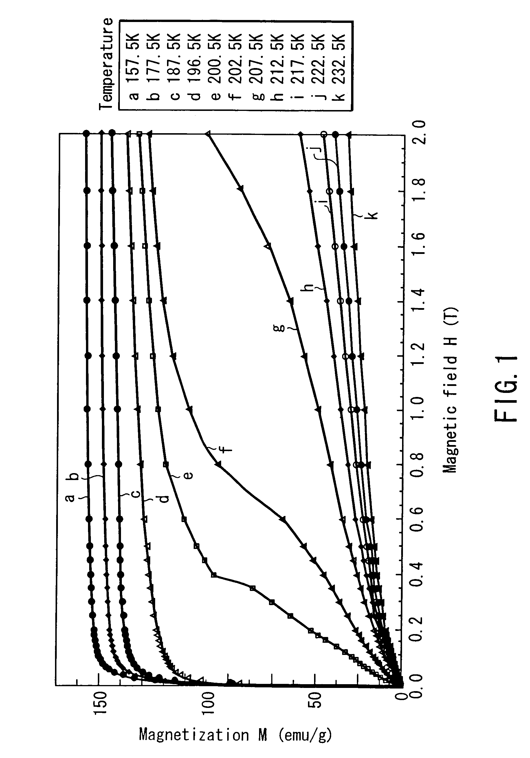
[0080]FIG. 1 shows the magnetization curves of specimen 1 at temperatures of 157.5 K to 232.5...

example 2

[0108]Three types of magnetic materials having the following compositions were manufactured, and these materials were tested for their magnetization curves and entropy changes due to magnetic field changes. In the following specimens, specimens 11 and 12 are magnetic materials based on the present invention, and specimen 13 is a comparative example.

[0109]Specimen 11: Fe67Hf28Ta5

[0110]Specimen 12: Fe67Hf27Ta6

[0111]Specimen 13: Fe67Hf29Ta4

[0112]After these materials having the above compositions were adjusted by arc melting, they were subjected to uniformization annealing in a vacuum at a temperature of 950° C. to 1,000° C. for about 100 hr, thereby manufacturing base alloys. From these base alloys, granular specimens were manufactured by using a plasma spray process. As a consequence, a large number of sphere particles having a long diameter of about 0.1 mm to about 0.3 mm were obtained. These specimens thus manufactured were tested for their magnetization curves.

[0113]FIG. 5 show...

example 3

[0123]Two types of magnetic materials having the following compositions were manufactured, and these materials were tested for their magnetization curves and entropy changes due to the change in external magnetic field.

[0124]Specimen 21: Mn63.4Cr3.3Sb33.3

[0125]Specimen 22: Mn50As35Sb15

[0126]The raw materials in powdery form having the above compositions were mixed, sealed in a crucible, and kept at a temperature of 800° C. to 950° C., generating chemical reaction slowly for a long period (about 2 days for specimen 21, about 1 week for specimen 22). Specimen 21 and 22 were subjected to uniformization annealing in a vacuum at a temperature of 550° C. to 700° C. for about 100 hr. These specimens thus manufactured were tested for their magnetization curves.

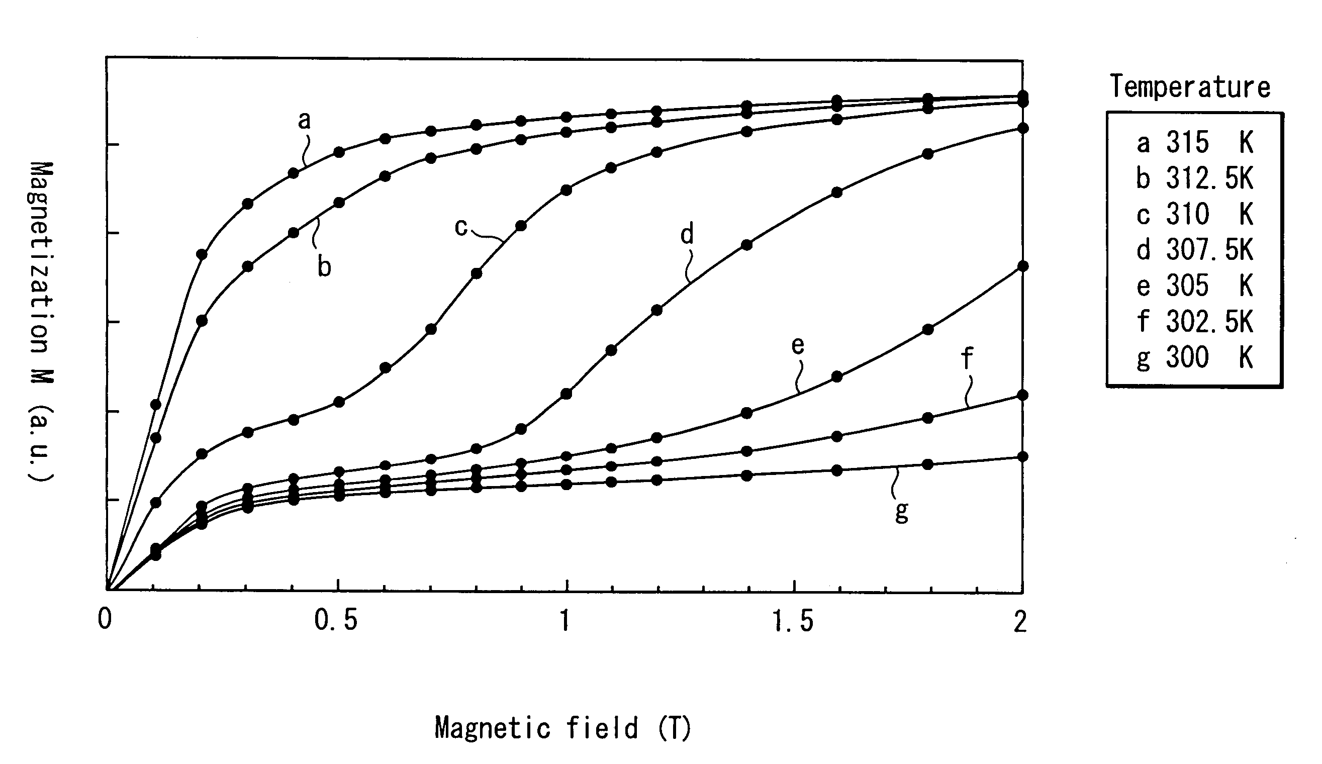
[0127]FIG. 7 shows the magnetization curves of specimen 21 at temperatures of 300 K to 315 K. The magnetization curves of specimen 21 at temperature of 315 k indicated that, within the range of magnetic field of 1 tesla or less, a s...


PUM

PropertyMeasurementUnit
magnetic fieldaaaaaaaaaa
temperatureaaaaaaaaaa
magnetic fieldaaaaaaaaaa

Abstract

The magnetic material for magnetic refrigeration of the present invention is characterized by exhibiting, in a certain temperature region, preferably, only in part of a temperature region from 200 K to 350 K, an inflection point at which a second order differential coefficient of a magnetization curve changes from positive to negative with respect to a magnetic field, within the range of this magnetic field formed using a permanent magnet unit. This magnetic material of the present invention can generate a low temperature by using a relatively low magnetic field, by transferring the entropy between the electron spin system and the lattice system near the temperature at which an inflection point appears on the magnetization curve. Examples of the magnetic material meeting this condition are La(Fe,Si)13, (Hf,Ta)Fe2, (Ti,Sc)Fe2, and (Nb,Mo)Fe2, each containing 50 to 60 atomic % of transition metals such as Fe.

Description

[0001]The present application is a continuation of application Ser. No. 10 / 098,568 filed Mar. 18, 2002 now U.S. Pat. No. 6,676,772.CROSS-REFERENCE TO RELATED APPLICATIONS[0002]This application is based upon and claims the benefit of priority from the prior Japanese Patent Application No. 2001-090953, filed Mar. 27, 2001, the entire contents of which are incorporated herein by reference.BACKGROUND OF THE INVENTION[0003]1. Field of the Invention[0004]The present invention relates to a magnetic material and, more particularly, to a magnetic material capable of realizing magnetic refrigeration using a relatively low magnetic field in near room temperature region.[0005]2. Description of the Related Art[0006]Presently, a gas compression / expansion cycle is primarily used in refrigeration systems, e.g., refrigerators, freezers, and air-conditioners, closely related to daily human life. However, this gas compression / expansion cycle is environmentally problematic, in terms of the exhaustion o...

Claims


Application Information

Patent Timeline
Patent Type & Authority Patents(United States)
IPC IPC(8): F25B21/00C09K5/00H01F1/04H01F1/01
CPCH01F1/015F25B21/00Y02B30/66Y02B30/00
Inventor SAITO, AKIKOKOBAYASHI, TADAHIKOSAWA, TAKAOSAHASHI, MASASHI
Owner KK TOSHIBA
Why Eureka
Try Eureka