Multi-cylinder engine

a multi-cylinder engine and engine technology, applied in the direction of machines/engines, crankshafts, auxillaries, etc., can solve the problems of increasing the weight of the engine in the axial direction of the crankshaft, increasing the scale, etc., to reduce the load capacity of the metal bearing, reduce the weight of the engine, and reduce the scale

Inactive Publication Date: 2006-07-18
HONDA MOTOR CO LTD
View PDF3 Cites 6 Cited by
  • Summary
  • Abstract
  • Description
  • Claims
  • Application Information

AI Technical Summary

Benefits of technology

[0007]The present invention has been made in view of such a circumstance as described above. It is an object of the present invention to provide a multi-cylinder engine wherein a decrease in the load capacity of a metal bearing between a bearing portion of a crankcase and a crank journal is prevented to achieve a reduction in scale and a reduction in the weight of the engine while lubricating oil can be supplied between a major end portion of a connecting rod and a crankpin.
[0011]According to the present invention, the pair of outermost crank journals disposed most outwardly along the axial line of the crankshaft from among the plurality of crank journals do not have a significant influence on an increase in the scale of the engine in the direction along the axial line of the crankshaft even if the length thereof in the axial direction is set to be long to some degree. Further, the crankpin oil paths extending to the crankpins from at least one of the outermost crank journals whose length in the axial direction is set comparatively great in this manner are provided in the crankshaft. Therefore, for each of the remaining crank journals, it is unnecessary to provide an annular oil groove on a main metal bearing for allowing communication of oil with the crankpin oil path. Therefore, even with the remaining crank journals whose length in the axial direction is set comparatively small, the load capacity of the main metal bearings can be assured sufficiently. Accordingly, it is possible to prevent a reduction of the load capacity of all of the main metal bearings and to achieve a reduction in the scale and a reduction in the weight of the engine while the lubricating oil can be supplied between the major end portions of the connecting rods and the crankpins.
[0012]Further, according to the present invention, the pistons are cooled by the oil jets while a sufficient amount of oil can be supplied between the major end portions of the connecting rods and the crankpins, which can contribute to an improvement in durability.

Problems solved by technology

This gives rise to an increase in the scale and an increase in the weight of the engine in the axial direction of the crankshaft.

Method used


Image

  • Multi-cylinder engine
  • Multi-cylinder engine
  • Multi-cylinder engine

Examples


Embodiment Construction

[0027]An embodiment of the present invention is described in connection with a working example of the present invention shown in the accompanying drawings.

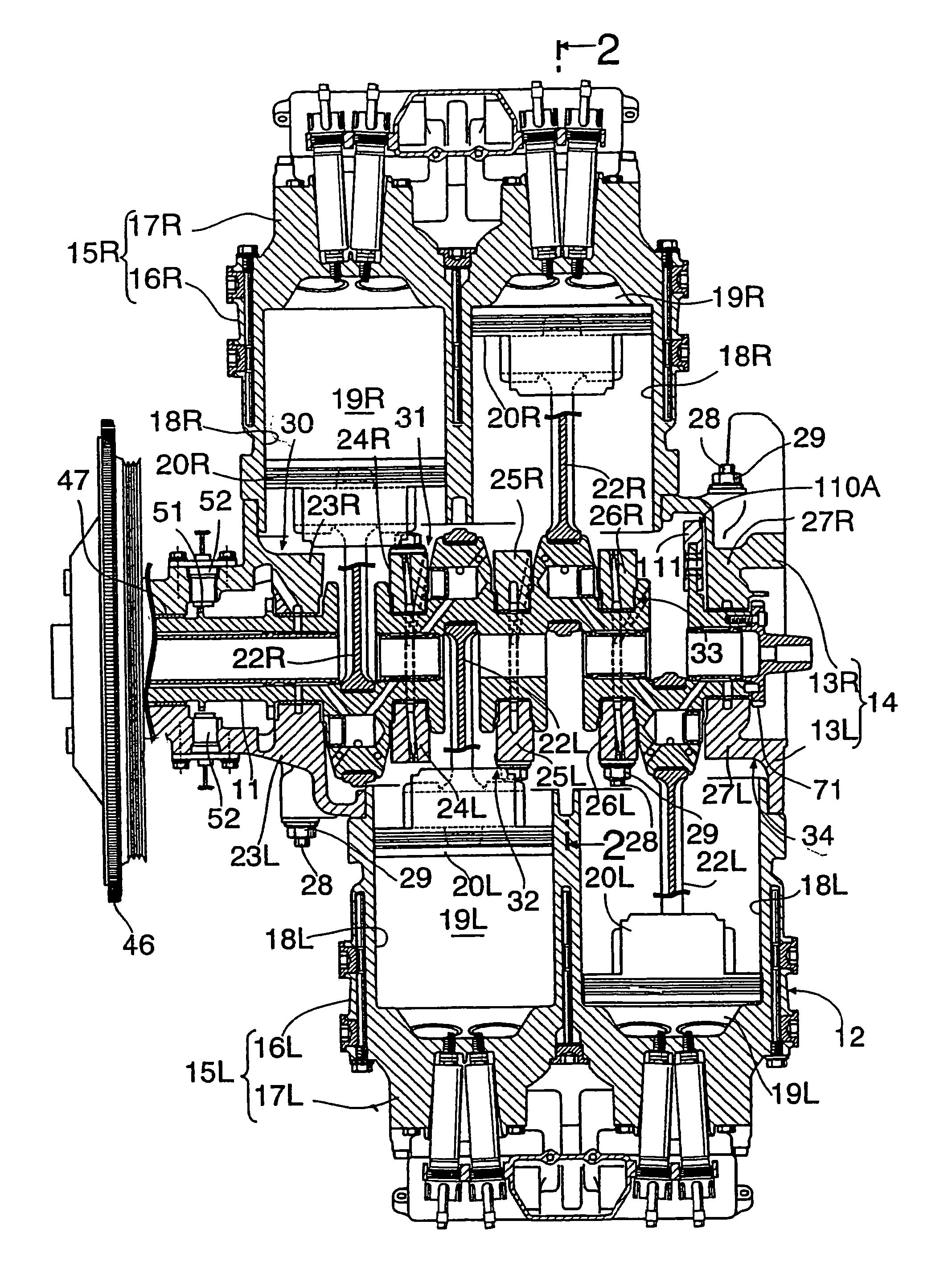
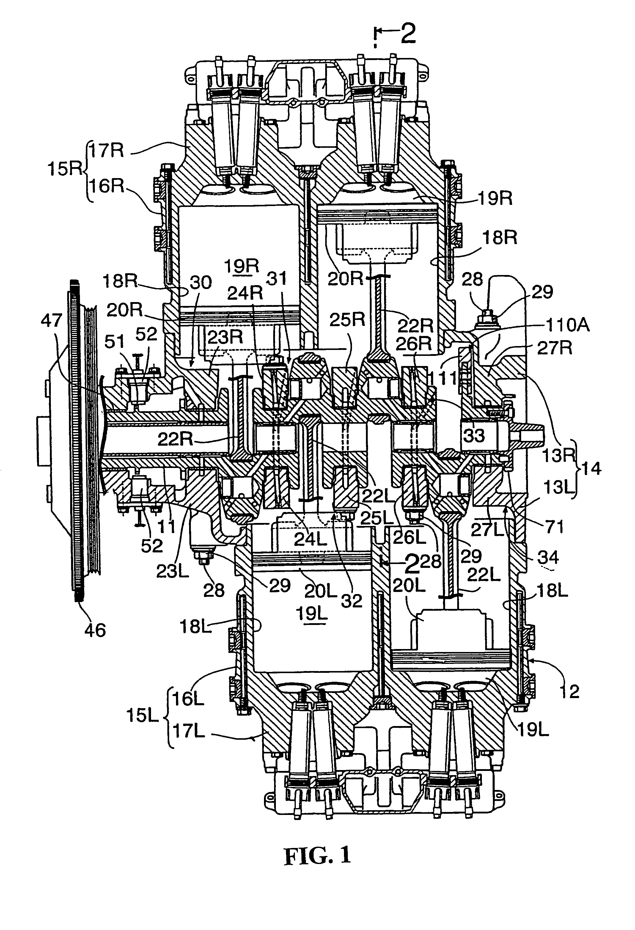
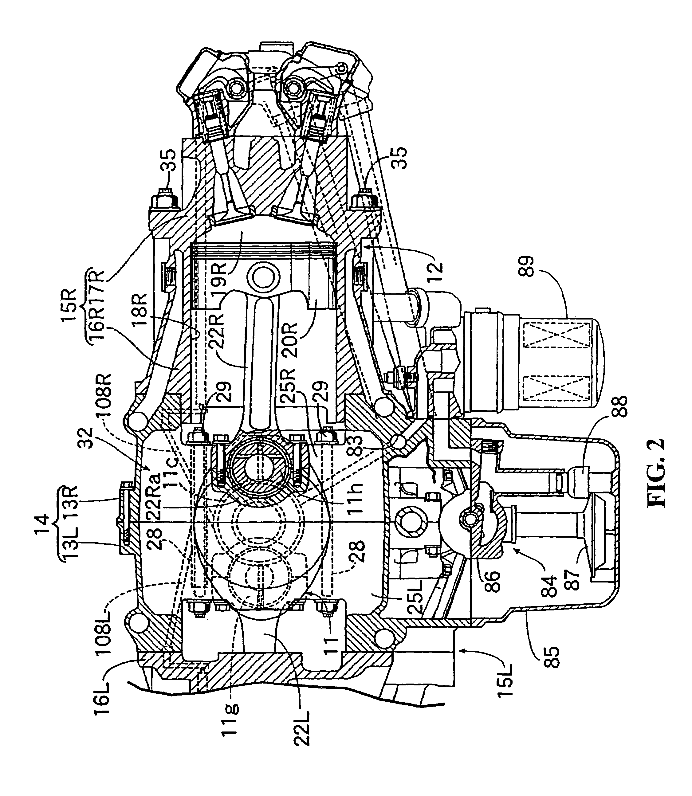
[0028]FIGS. 1 to 9 show a working example where the present invention is applied to a four-cycle horizontally opposed type four-cylinder engine.

[0029]Referring first to FIGS. 1 and 2, the four-cycle horizontally opposed type four-cylinder engine is incorporated, for example, in an airplane and accommodated in a front cowl of a body of the airplane such that an axial line of a crankshaft 11 extends in a forward and rearward direction. A spinner having a plurality of propellers is coupled coaxially to the crankshaft 11.

[0030]An engine body 12 of the engine includes a crankcase 14 formed such that a left case half 13L disposed on the left side as the engine as viewed from the rear side and a right case half 13R disposed on the right side as the engine as viewed from the rear side are coupled to each other. The engine body 12 of the e...


PUM


Abstract

In a multi-cylinder engine, a decrease of the load capacity of a main metal bearing between a bearing portion of a crankcase and a crank journal is prevented to achieve a reduction in the scale and a reduction in the weight of the engine while lubricating oil is supplied between a major end portion of a connecting rod and a crankpin. A pair of outermost crank journals are disposed most outwardly along an axial line of a crankshaft from among a plurality of crank journals have a length in the axial direction set greater than the length of the remaining crank journals in the axial direction. Crankpin oil paths extending from at least one of the two outermost crank journals to the crankpins are provided in the crankshaft while an oil supply source is connected to the crankpin oil paths at least at one of the outermost crank journals.

Description

CROSS-REFERENCE TO RELATED APPLICATIONS[0001]The present application claims priority under 35 USC 119 to Japanese Patent Application No. 2003-279671 filed on Jul. 25, 2003 the entire contents thereof is hereby incorporated by reference.BACKGROUND OF THE INVENTION[0002]1. Field of the Invention[0003]This invention relates to a multi-cylinder engine, and more particularly to a multi-cylinder engine wherein a crankshaft is provided on which a plurality of crank journals are individually rotatably supported through main metal bearings on a plurality of bearing portions provided on a crankcase and crankpins to which major end portions of connecting rods are integrally provided and are connected for pivotal motion. The crankpin oil paths are provided for supplying lubricating oil between the major end portions of the connecting rods and the crankpins.[0004]2. Description of Background Art[0005]Conventionally, in a multi-cylinder engine disclosed, for example, in Japanese Patent Laid-open ...

Claims


Application Information

Patent Timeline
Patent Type & Authority Patents(United States)
IPC IPC(8): F01M1/06F01P1/04F01M1/08F01M11/02F01P3/08F02F1/00F02F7/00F16C3/08F16C3/14
CPCF01M1/06F01M2001/062F01P3/08F01M2011/026F01M2011/027F01M2011/025
Inventor MATSUDA, MINORU
Owner HONDA MOTOR CO LTD
Why Eureka
Try Eureka