

Block impact splitter
a technology of impact splitter and block, which is applied in the direction of wood splitting, stone-like material working tools, metal working apparatuses, etc., can solve the problems of body injuries, dangerous operation, and excessive material was
- Summary
- Abstract
- Description
- Claims
- Application Information
AI Technical Summary
Benefits of technology
Problems solved by technology
Method used
Image

Examples
Embodiment Construction
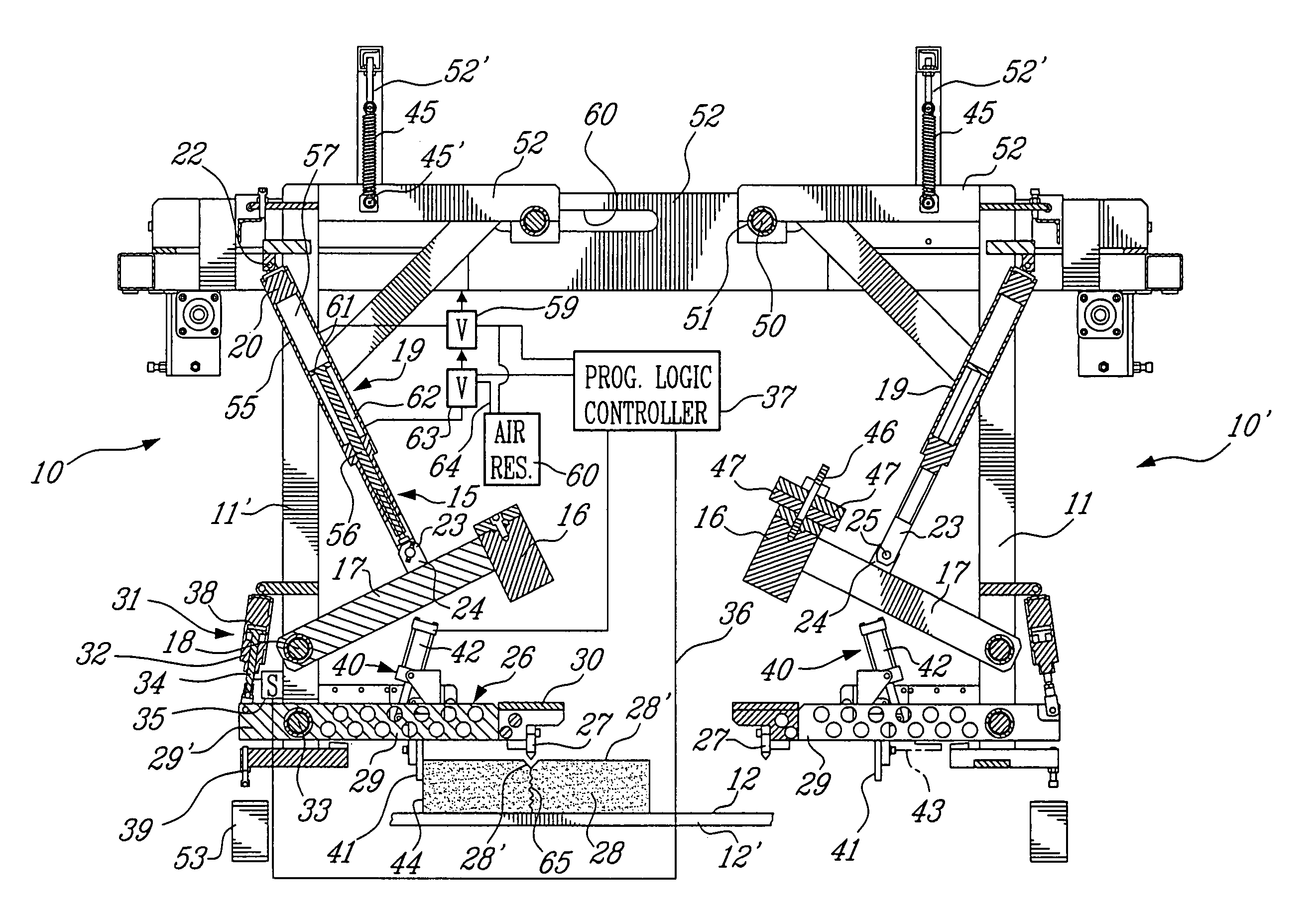
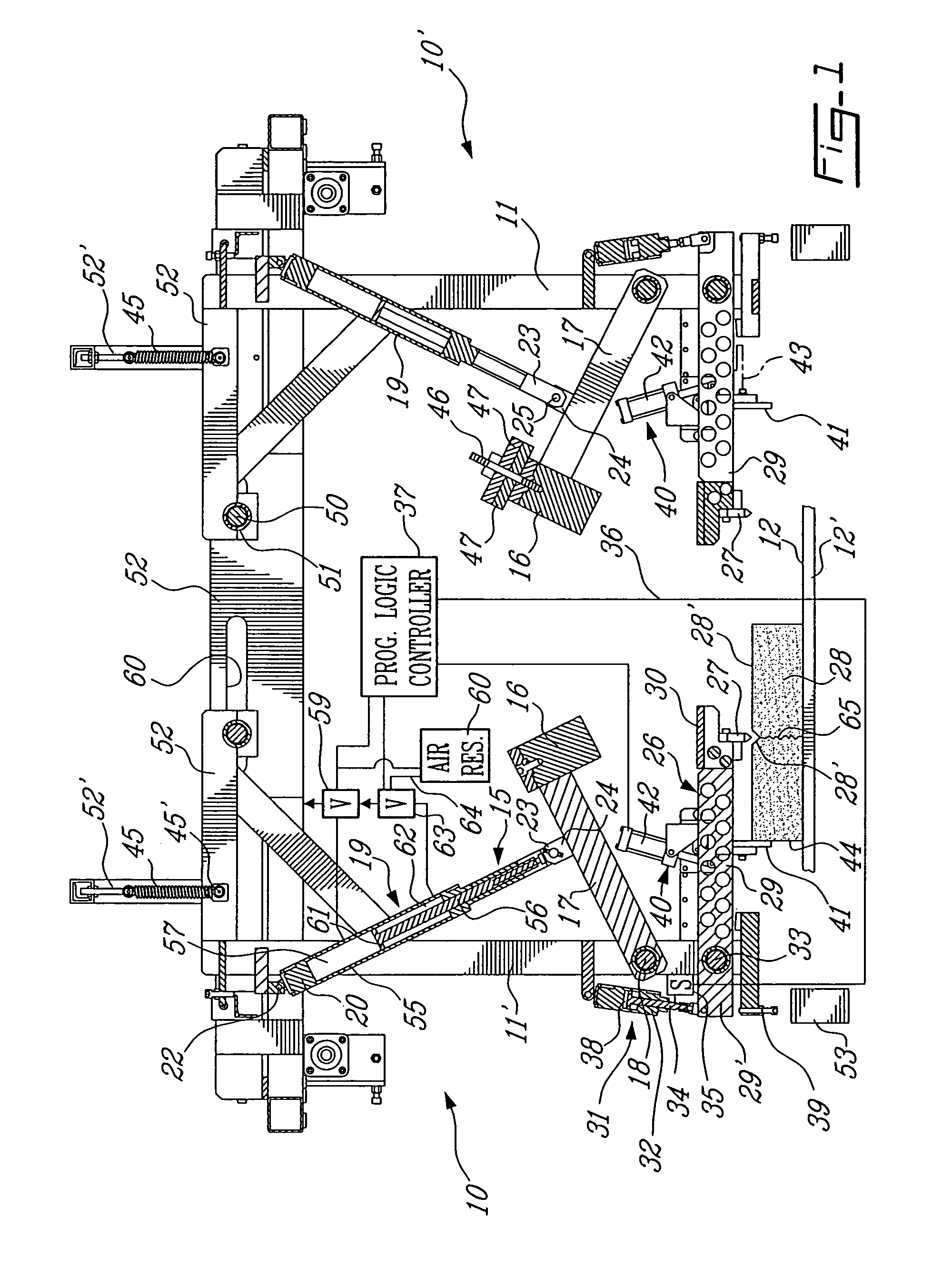
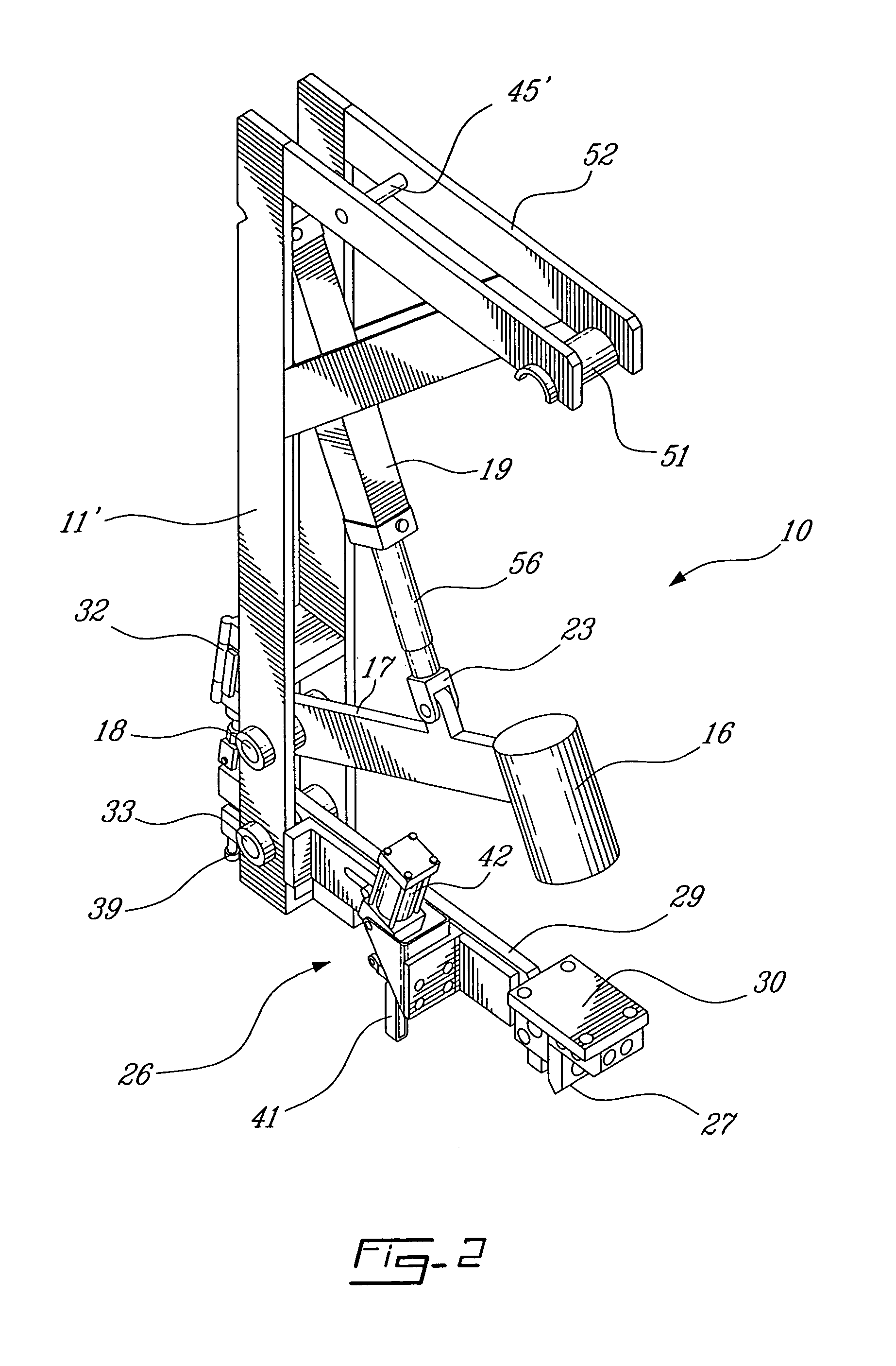
[0016]Referring now to the drawings and more specifically to FIGS. 1 and 2, there is shown generally at 10 a block impact splitter constructed in accordance with the present invention. As illustrated in FIG. 1, there are two block impact splitters 10 and 10′ secured in transverse alignment with one another on support frames 11 and 11′, respectively. A block support surface 12 is disposed at a precise position relative to the frame 11. The block support surface 12 is herein constituted by a block support production plate 12′ which is displaceable under the frame 11 by displaceable support means which, as shown in FIG. 3, is provided by a carriage 13 displaceable on tracks 14 disposed under the frame 11. However, other types of mechanisms can be provided to position the plate under the splitters 10 and 10′. An important feature of the present invention is that the blocks are casted on their production plate 12′, transported and split without having to be transferred to another support...
PUM
| Property | Measurement | Unit |
|---|---|---|
| impact force | aaaaa | aaaaa |
| displacement | aaaaa | aaaaa |
| weight | aaaaa | aaaaa |
Abstract
Description
Claims
Application Information