
Horizontal continuous casting of metals

a technology of metals and casting ingots, applied in the field of horizontal continuous casting of metals, can solve the problems of irregular surface on the cast ingot, molten metal “breakout” may occur, surface defects, etc., and achieve the effects of reducing reducing the heat flux between the metal and the mould walls, and minimizing the detrimental effect of lubricant reaction

Active Publication Date: 2006-07-18
NOVELIS INC
View PDF17 Cites 6 Cited by
  • Summary
  • Abstract
  • Description
  • Claims
  • Application Information

AI Technical Summary

Benefits of technology

The present invention relates to a mold for horizontal casting of molten metal. The mold has a permeable wall member with an inner face forming an interior face of the mold. A refractory transition plate is mounted at the inlet end of the mold to provide a mold inlet opening. A gas conduit is fed through the inlet opening and a separate conduit is fed to feed gas into the permeable wall member. A lubricant is fed through a conduit to flow into the permeable wall member. The gas fed to the shoulder and the inner face of the mold forms a pocket of metal-free space behind the metal meniscus. The gas fed to the inner face of the mold is more reactive with molten aluminum than the gas fed to the shoulder. The use of two gas stages generates a strong supporting reaction product film on the surface of the molten metal meniscus, while minimizing the detrimental effects of lubricant reaction with the gas. This results in a high surface temperature and rapid solidification of the billet. The invention also relates to a cast billet product with a uniform microstructure and smooth surface. The amount of lubricant added is low, and detectors are used to measure the electrical resistance between the mold cavity wall and molten metal in the mold to vary the flow of lubricant based on the measured resistance.

Problems solved by technology

Injection of gas in such moulds can cause the oxide that forms on the surface of the emerging ingot to be unequally formed around the periphery of the emerging ingot with the resulting formation of surface defects.
For instance, an inconsistent or uneven outer shell or skin within a mould may stick to the mould resulting in an irregular surface on a cast ingot or “break out” of molten metal may occur.

Method used


Image

  • Horizontal continuous casting of metals
  • Horizontal continuous casting of metals
  • Horizontal continuous casting of metals

Examples


Embodiment Construction

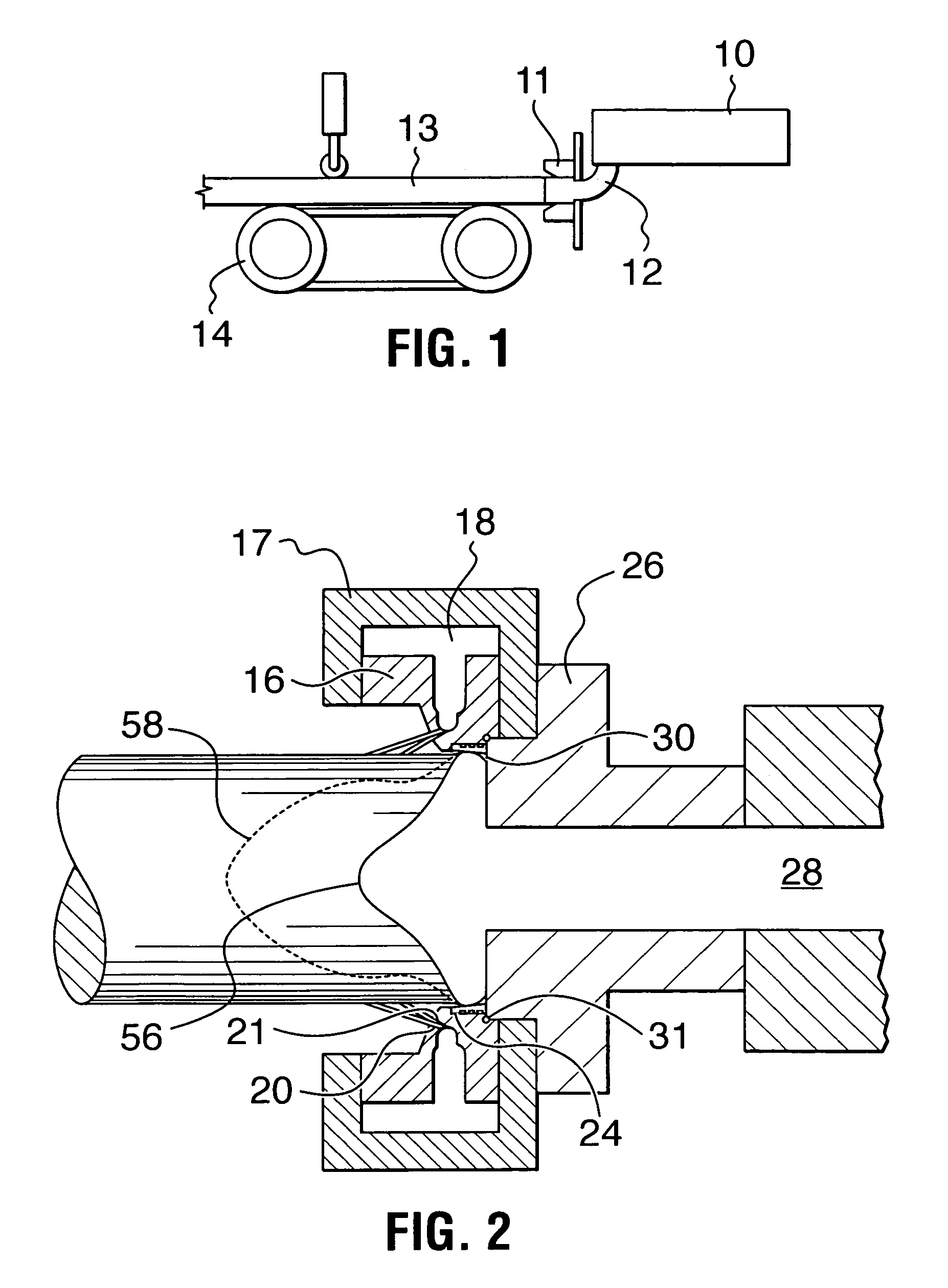
[0035]FIG. 1 shows a typical horizontal casting mould of the type to which the present invention relates, including an insulated molten aluminum reservoir 10, an inlet trough 12 and a horizontal casting mould 11. An ingot 13 is delivered from the mould and is carried from the mould by a conveyor 14.

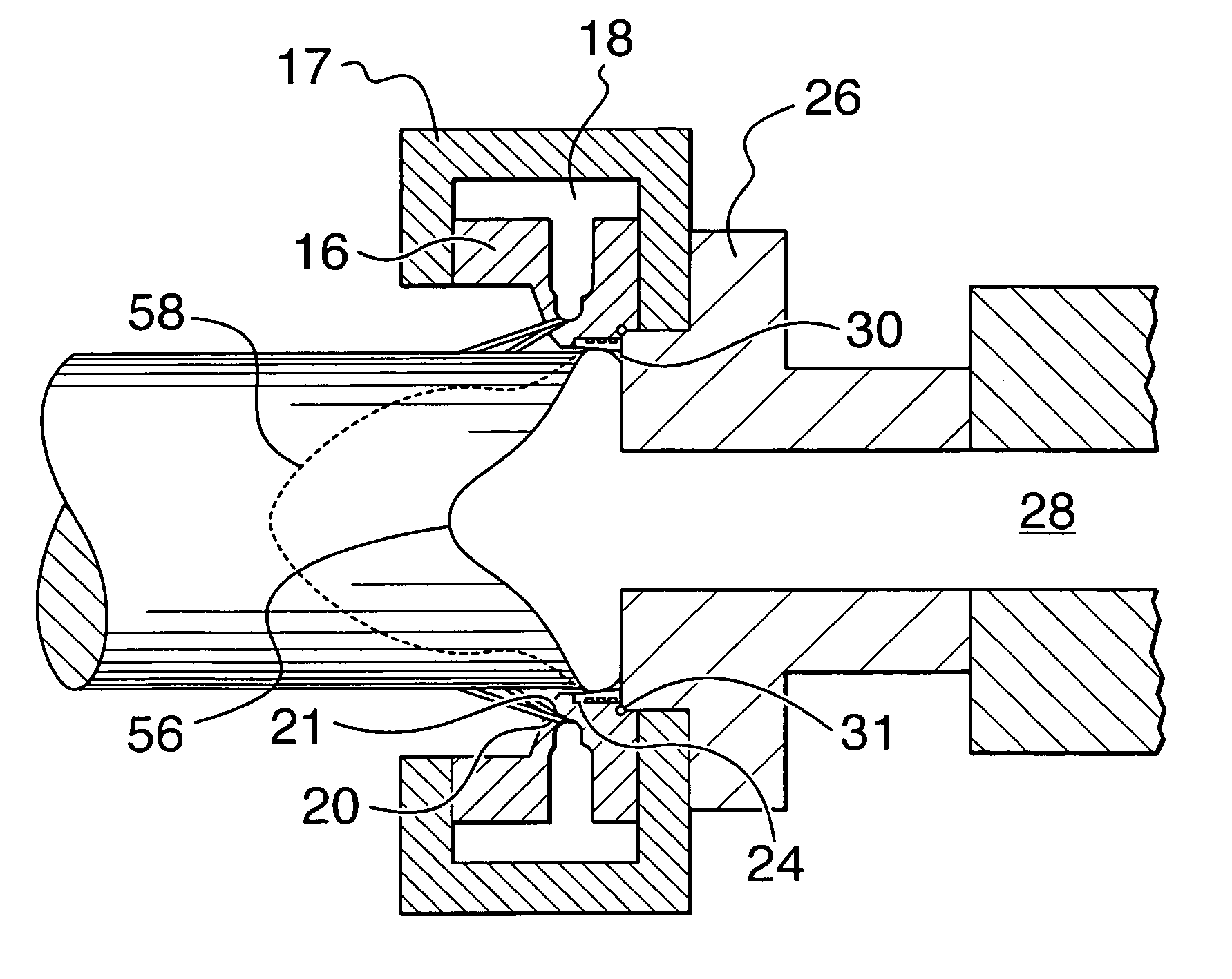
[0036]In FIG. 2 a two-part mould body 16, 17 is shown, in which is contained a water channels 18 fed by coolant delivery pipe (not shown) and communicating with a set of staggered coolant outlet holes 20, 21 around the periphery of the mould body.

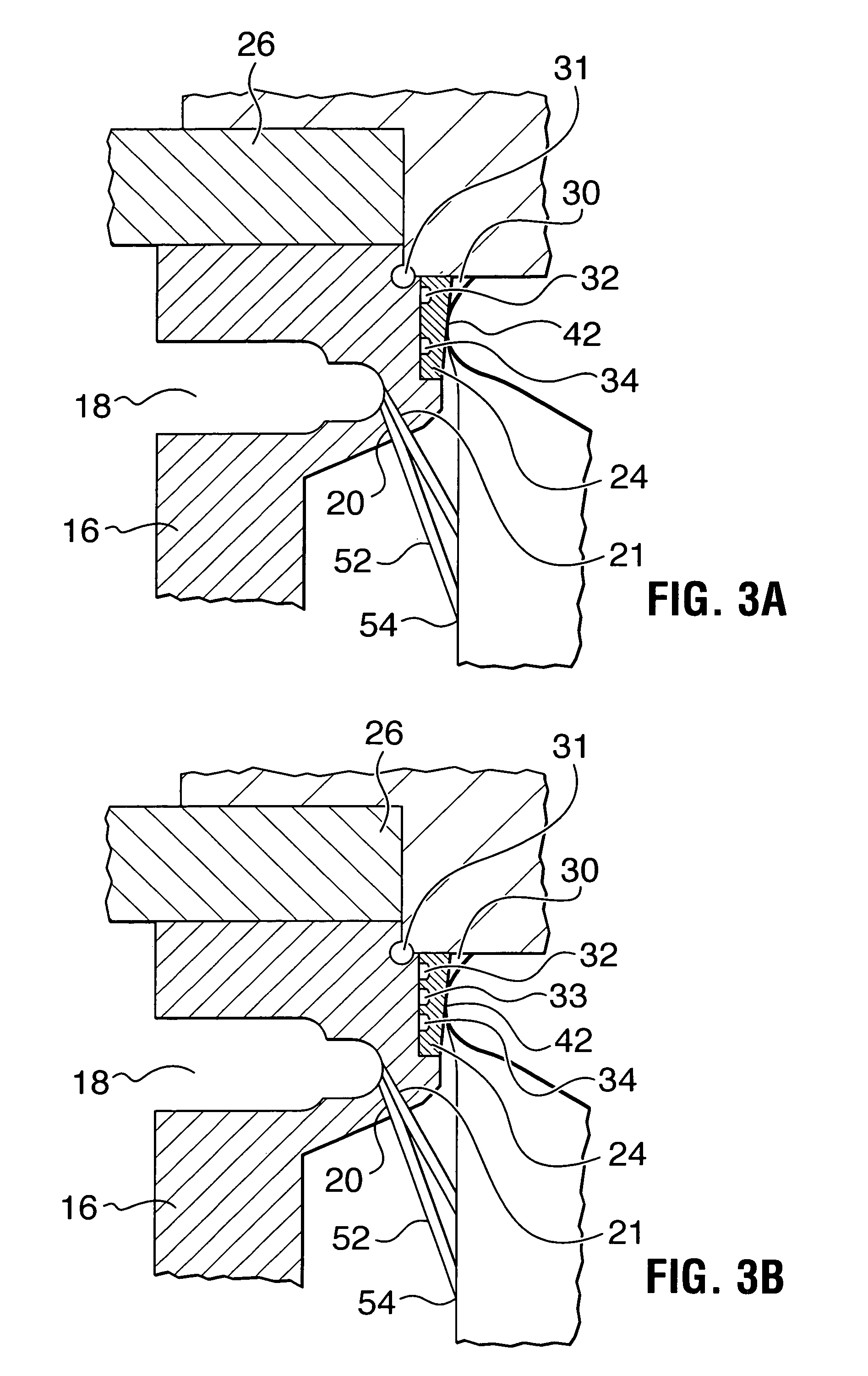
[0037]A tapered permeable graphite annular ring 24 is mounted inside the mould body 16 so as to form an inner surface to the mould. A transition plate 26 formed from refractory material is mounted at the upstream. (or metal entry end) 28 of the mould. It has a smaller interior cross-sectional opening than the annular ring 24 thereby forming a shoulder and pocket 30 in the corner of the mould. An O-ring seal 31 is provided at the intersection of t...


PUM

PropertyMeasurementUnit
average cell-sizeaaaaaaaaaa
surface roughnessaaaaaaaaaa
lengthaaaaaaaaaa

Abstract

A mold for horizontal casting of molten metal comprising a mold body forming an open-ended mold cavity having an inlet end and an outlet end. An annular permeable wall member is mounted in the mold body adjacent the inlet end of the mold cavity with an inner face thereof forming an interior face of the mold. A refractory transition plate is mounted at the inlet end of the mold cavity, this transition plate providing a mold inlet opening having a cross-section less than that of the mold cavity. This provides an annular shoulder at the inlet end of the cavity. Means are provided for feeding molten aluminum through the inlet opening. Separate conduits are also provided for feeding a gas into the shoulder and via the permeable wall means for providing a layer of gas between the metal and the inner face of the mold. A gas that is more reactive with molten aluminum is fed into the shoulder and a less reactive gas is fed via the permeable wall. The reactions with the molten aluminum create a skin or shell on the aluminum which provides smooth passage through the mold and allows for more rapid secondary cooling of the emerging ingot.

Description

FIELD OF THE INVENTION[0001]This invention relates to horizontal continuous casting of metals, particularly light metals such as aluminum and its alloys.DESCRIPTION OF THE PRIOR ART[0002]In the continuous horizontal casting of metals, such as aluminum, the molten metal is held in an insulated reservoir and from there is fed into the inlet end of a horizontal open-ended mould cavity having a generally horizontal axis. Within the mould cavity the molten metal is initially chilled sufficiently to form a metal body comprising an outer skin or shell surrounding a still molten metal core. As this metal body emerges from the mould cavity, it is sprayed with liquid coolant, e.g. water, for further cooling and solidification.[0003]The molten metal is fed into the mould cavity through an opening or nozzle having a smaller cross-section than that of the mould cavity, such that a lip or overhang is formed at the inlet end of the mould cavity. This metal inlet nozzle is typically a refractory pl...

Claims


Application Information

Patent Timeline
Patent Type & Authority Patents(United States)
IPC IPC(8): B22D11/00B22D7/00B22D11/04B22D11/045B22D11/049B22D11/07B22D11/117B22D21/04B22D27/00
CPCB22D11/0401B22D11/07B22D11/049B22D11/045B22D11/00B22D21/04
Inventor BOWLES, WADE LEEHAMBY, JACKFISCHER, ALEXANDER J.SALEE, DAVID A.
Owner NOVELIS INC
Learn More