Multifuncional environmental control unit

Active Publication Date: 2018-06-19
HUNKA ROBERT
View PDF10 Cites 13 Cited by
  • Summary
  • Abstract
  • Description
  • Claims
  • Application Information

AI Technical Summary

Problems solved by technology

A similar delay in response occurs due to poor air induction movement at diffuser room element under low supply pressure conditionsG.
As a result of mechanical friction or wax chemistry induced hysteresis, detrimental control dead band, as well as, time delays are created.
Because of the use of lever arms in the assembly, high external force can act on the wax actuators and cause operational changes over time and life expectancy deterioration.
Velocity that is too low will result to temperature stratification.
Velocity that is high can result in drafty conditions in the cooling mode.
While cooling from the ceiling with a horizontal throw pattern is good, driving heated air along the ceiling and down a wall (particularly down a cold window) may be difficult.B.
Partitioning individual spaces within an open office with cubicles can be difficult when adjacent ceiling diffusers compete and can over-ride each others thermal control operations
The sheet metal construction for the typical throttling surfaces are not perfectly straight or in good alignment and can create high pitch audible whistling at nearly closed conditions
If the appearance panel, blocking the internal mechanism, is noticeably below the plane of the ceiling, the continuous look is also disrupted.B.
Painted sheet metal, if not properly handling can be scratched requiring touch up or replacement.
Colors and textures are limited f

Method used


Image

  • Multifuncional environmental control unit
  • Multifuncional environmental control unit
  • Multifuncional environmental control unit

Examples


Example

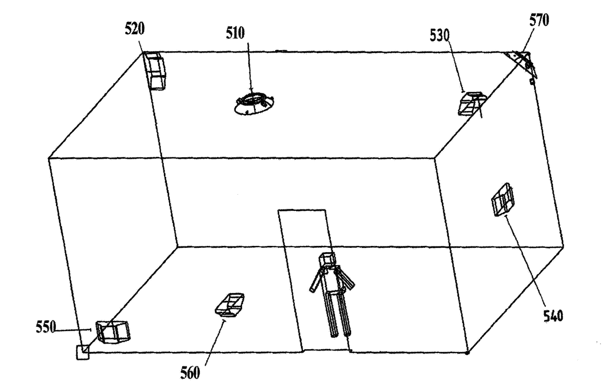
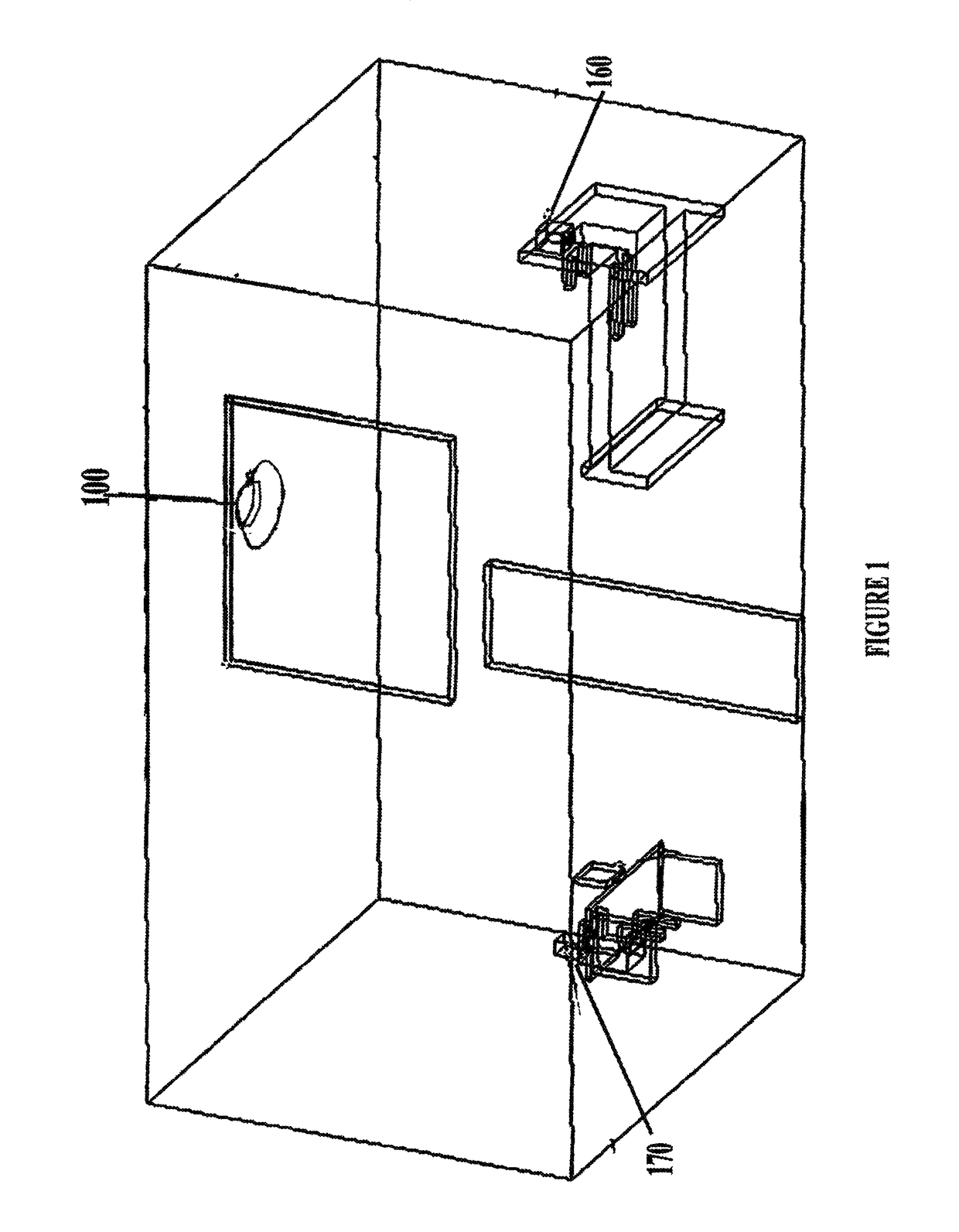
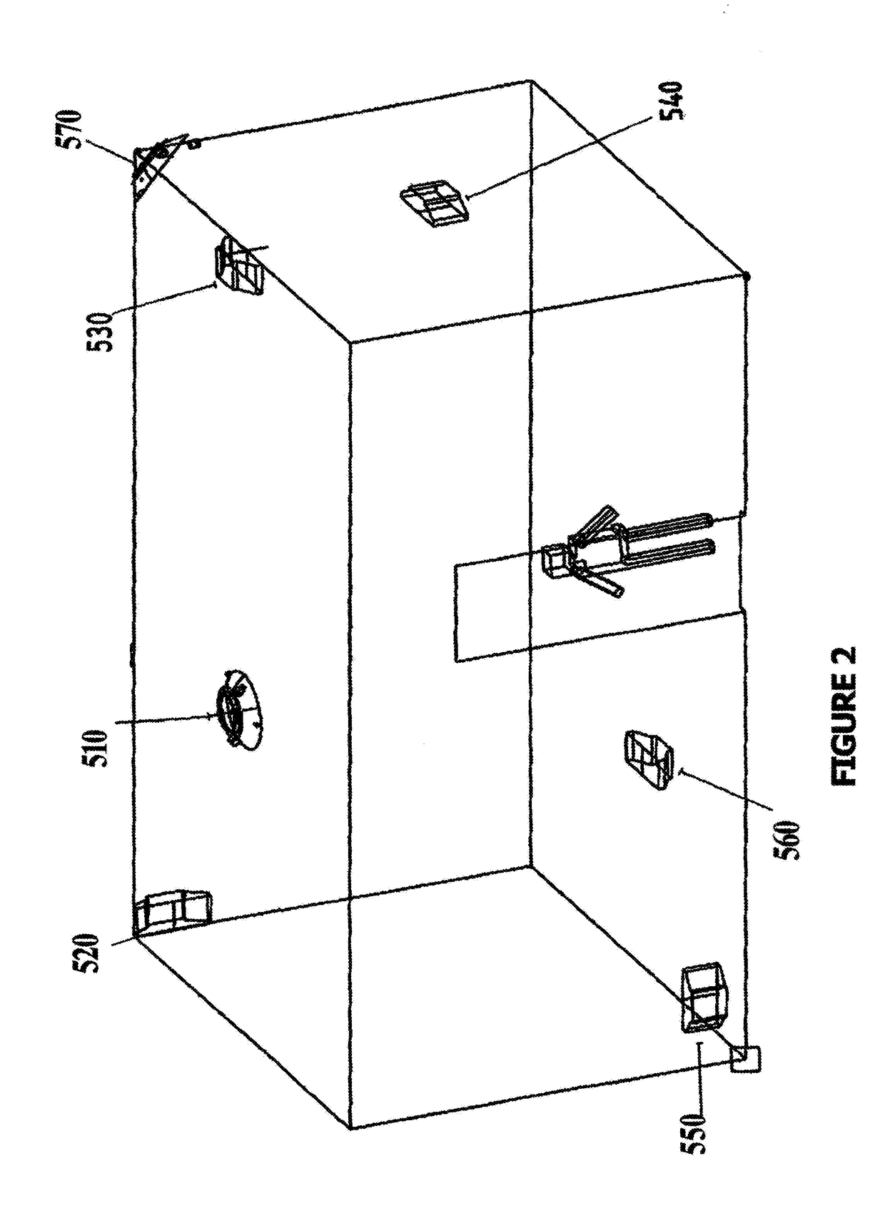
[0091]While describing the invention and its embodiments, various terms will be used for the sake of clarity. These terms are intended to not only include the recited embodiments, but also all equivalents that perform substantially the same function, in substantially the same manner to achieve the same result.[0092]A. Now referring to FIG. 1 which discloses a preferred embodiment of the present invention, an air diffuser housing assembly generally referenced by numeral 100 which is depicted in a closed environment, such as a room or office wherein the unit 100 has the functionality of the following, it can sense external and internal properties, such as temperature, pressure, and position, and control the movement of conditioned air for thermal control Occupants, referenced by numerals 170 and 160, will benefit from the multi-functional capabilities of the an air diffuser housing assembly.[0093]B. Now referring to FIG. 2 which discloses optional locations for the controlling unit. O...


PUM


Abstract

A novel multifunctional electromechanical device to monitor and control environmental conditions within an occupied space. This device can be configured as a standard VAV Diffuser, an intelligently controlled window, or an intelligently controlled shutter. Functions include thermal control, and air quality control. The device would be built and located to optimize functionality and satisfy the aesthetic needs of occupants, designers, and architects. Energy harvesting combined with ultra-low power operation would reduce the long term operational costs. Mechanical and electronic modularity would facilitate the incorporation of new functions and to upgrade existing functions to improve performance and reduce cost. Additionally, a gas flow damper device that would sense pressure differential integrally or remotely and intelligently control pressure differential. A self powered, energy harvesting damper could be used to balance pressures to various ones in an office space providing just enough air flow to satisfy each zone. Wireless node network would allow communication between multiple balancing dampers to create a highly collaborative network.

Description

[0001]This utility patent application claims the priority of provisional application of U.S. 61 / 631,388 filed on Jan. 3, 2012.BACKGROUND OF THE INVENTIONField of Invention[0002]I. The invention relates to environment control and regulation with multifunctional capability, specifically, but not limited to, an improved intelligent variable air volume device. Additionally, this invention relates to controlling the opening / closing of windows or dampers allowing introduction of clean air from another location (i.e. ambient outside air) to maintain acceptable indoor air quality (Indoor Air Quality Control Device) and / or the introduction of air at a different temperature for thermal control (Temperature Control Device). The pressure differential producing the air flow can be driven by wind, a fan blowing into the space, or a fan blowing outward creating a negative pressure, or the buoyancy forces create by temperature difference. When the temperature of an enclosed space with a tower, vent...

Claims


Application Information

Patent Timeline
IPC IPC(8): G05D25/00G05D23/19F24F11/00
CPCG05D23/19F24F11/0001F24F11/30F24F2110/10F24F2140/40F24F2120/10F24F11/46F24F11/64F24F11/67
Inventor HUNKA, ROBERT
Owner HUNKA ROBERT
Why Eureka
Try Eureka