
ZIF connector in which a position of a contact is automatically adjusted during a connecting operation

a technology of automatic adjustment of contact position and connector, which is applied in the direction of instrumentation, planar/plate-like light guide, and connection of coupling devices, to achieve the effect of smooth fitting first and easy prevention of connection errors

Inactive Publication Date: 2006-07-18
JAPAN AVIATION ELECTRONICS IND LTD +2
View PDF6 Cites 6 Cited by
  • Summary
  • Abstract
  • Description
  • Claims
  • Application Information

AI Technical Summary

Benefits of technology

The present invention provides a ZIF connector that automatically adjusts the position of contacts during connection, smoothly fits connectors even if misalignment occurs between contacts, and easily prevents connection errors between connectors. The connector comprises an insulator holding conductive contacts, an operating member, and a floating member rotatable and slidable in a predetermined direction. The floating member has one surface facing the conductive contacts and the operating member, and the other surface facing the second conductive contacts. The operating member rotates to bring the second conductive contacts into contact with the first conductive contacts when the connectors are fitted to each other. The second connector comprises an insulator holding the second conductive contacts, and the floating member rotates in a first rotating direction to bring the second conductive contacts into contact with the first conductive contacts. The first connector comprises an insulator holding the first conductive contacts, and the floating member rotates in a first rotating direction to bring the second conductive contacts into contact with the first conductive contacts.

Problems solved by technology

Further, the contacts may be undesiredly and improperly contacted with each other to cause connection error.

Method used


Image

  • ZIF connector in which a position of a contact is automatically adjusted during a connecting operation
  • ZIF connector in which a position of a contact is automatically adjusted during a connecting operation
  • ZIF connector in which a position of a contact is automatically adjusted during a connecting operation

Examples


Embodiment Construction

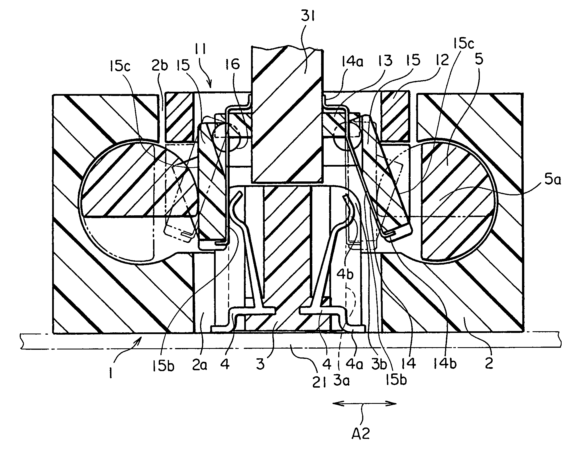
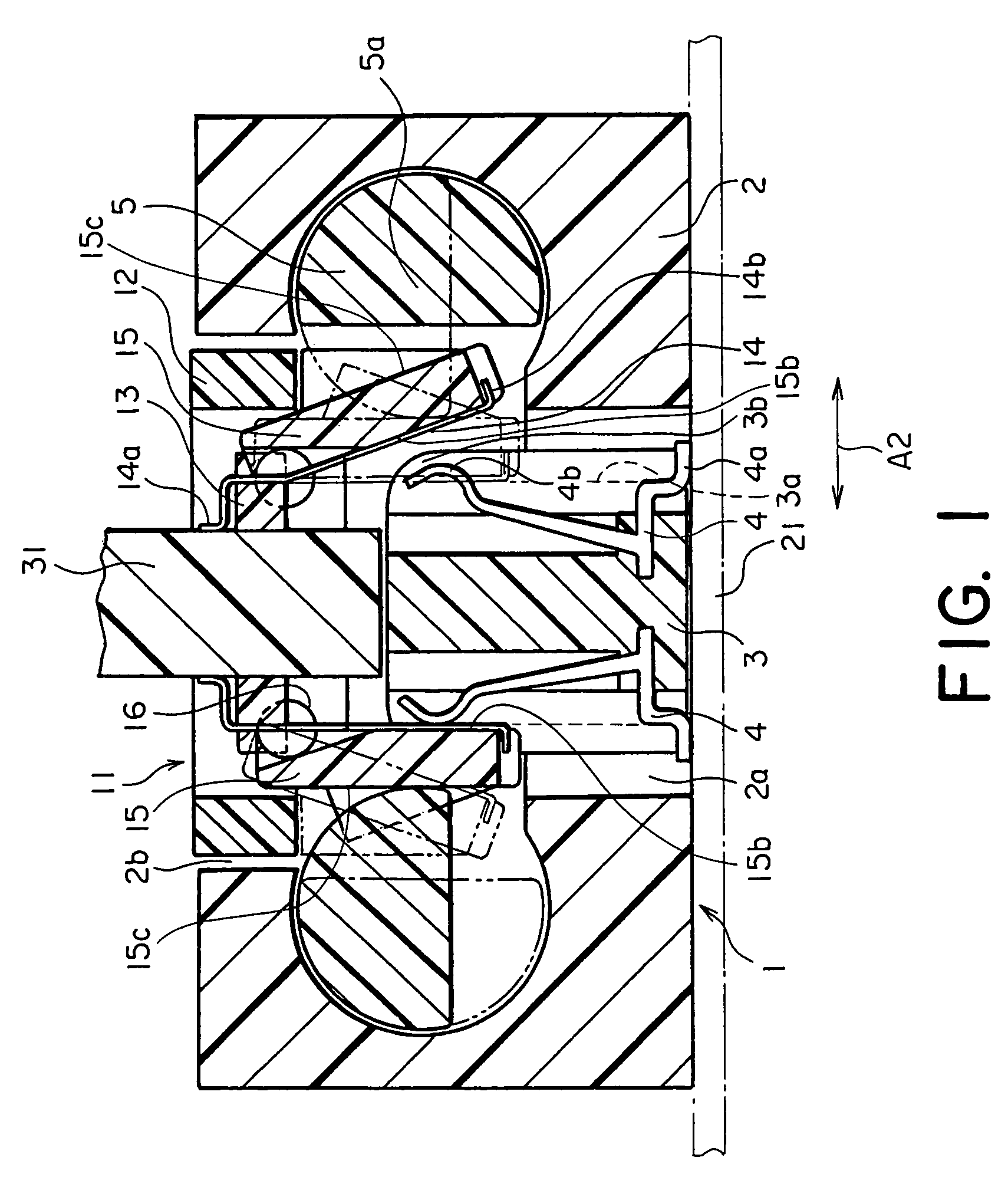
[0020]Referring to FIGS. 1 through 3, description will be made of a ZIF connector according to an embodiment of this invention.

[0021]The ZIF connector illustrated in the figure comprises a first connector 1 and a second connector 11 to be fitted and connected to the first connector 1. For convenience of description, a left half in FIG. 1 shows a state where the first and the second connectors 1 and 11 are fitted and connected to each other while a right half shows a state where the first and the second connectors 1 and 11 are fitted to each other but not connected.

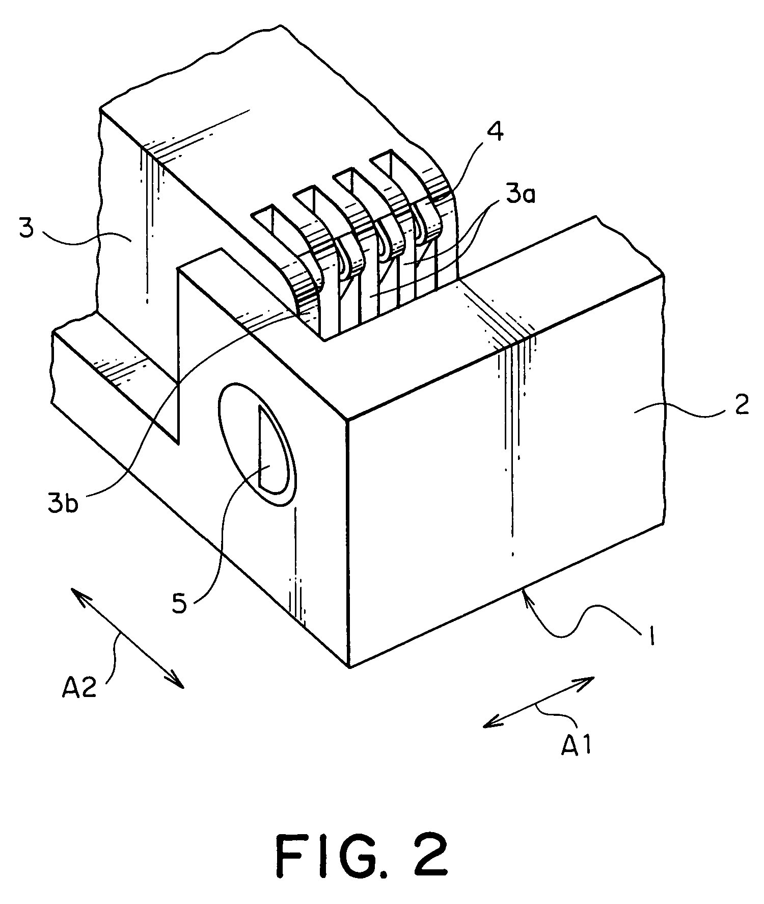
[0022]Referring to FIGS. 1 and 2, the first connector 1 is mounted to a mother board 21 and comprises a synthetic resin frame 2 and an insulator 3. A combination of the frame 2 and the insulator 3 may be referred to as a first insulator portion.

[0023]The frame 2 defines a lower space 2a and an upper space 2b at its center. Inside the frame 2, a pair of semicylindrical cams 5 are rotatably held on left and right sides to se...


PUM


Abstract

In a ZIF connector having first and second connectors, the first connector includes an operating member rotatably held by a first insulator portion holding first contacts arranged adjacent to one another in a predetermined direction. The second connector includes a floating member held by a second insulator portion to be rotatable and slidable in the predetermined direction. The floating member has a first and a second surface which face the first contacts and the operating member, respectively, in a mutually fitted state of the first and the second connectors. Second contacts have one parts held by the first surface and arranged adjacent to one another in the predetermined direction. The floating member is rotated in a first rotating direction to bring the second contacts into contact with the first contacts when the operating member is rotated in the mutually fitted state.

Description

[0001]This application claims priority to prior Japanese Patent Application JP 2004-10885, the disclosure of which is incorporated herein by reference.BACKGROUND OF THE INVENTION[0002]This invention relates to a so-called zero insertion force (ZIF) connector which requires only a small force for insertion and removal of connectors into and from each other.[0003]A ZIF connector of the type is disclosed in Japanese Unexamined Patent Application Publication (JP-A) No. 2000-340310. The ZIF connector comprises a first connector and a second connector to be fitted and connected thereto. The first connector has a plurality of contacts held by an insulator and arranged adjacent to one another in a predetermined direction. Generally, the contacts have a predetermined pitch. The insulator rotatably supports a driving member. The driving member has a plurality of cam portions.[0004]Similarly, the second connector has a number of contacts held by an insulator and arranged adjacent to one anothe...

Claims


Application Information

Patent Timeline
Patent Type & Authority Patents(United States)
IPC IPC(8): H01R13/15H01R24/00H01R13/193H01R13/64H01R13/641
CPCH01R13/193H01R12/88Y10S439/952G02B6/0015G02B6/0023G02B6/0051G02B6/0055
Inventor MAEDA, TOSHIHIKOMIZUSAWA, YOSHINORITAKAHASHI, ISAO
Owner JAPAN AVIATION ELECTRONICS IND LTD
Features
  • Generate Ideas
  • Intellectual Property
  • Life Sciences
  • Materials
  • Tech Scout
  • Unparalleled Data Quality
  • Higher Quality Content
  • 60% Fewer Hallucinations
Learn More