
Continuously variable transmission

Inactive Publication Date: 2006-07-18
NSK LTD
View PDF13 Cites 118 Cited by
  • Summary
  • Abstract
  • Description
  • Claims
  • Application Information

AI Technical Summary

Benefits of technology

[0017]The invention has been devised in view of the above-described circumstances, and its object is to provide a continuously variable transmission which does not impart an uncomfortable feeling to the driver by suppressing the occurrence of a speed change shock by obtaining stable variations of torque in the mode change.

Problems solved by technology

As this power roller moves in the vertical direction, side slippage occurs, with the result that the power roller undergoes a speed change.(2) In addition, the transmission ratio changes with respect to the load of the torque due to the effect of the deflection of a trunnion shaft caused by the resilient deformation of the trunnion.
Consequently, although a trunnion shaft itself is not resiliently deformed since it is not subjected to forces, but the trunnion shaft is affected by the resilient deformation of the trunnion, with the result that the trunnion shaft becomes inclined.
In consequence, the valve is cut, and the differential pressure occurs, resulting in the occurrence of the speed change.
However, the situation must be avoided in which control becomes unstable at the time of the mode change, i.e., when the torque has varied.
Accordingly, if the time duration of connection and disconnection of the clutch is long in the mode change, the state becomes such that no power is being generated, so that the driver feels a sense of uncomfortableness due to such as the revving up of the engine.

Method used


Image

  • Continuously variable transmission
  • Continuously variable transmission
  • Continuously variable transmission

Examples


first embodiment

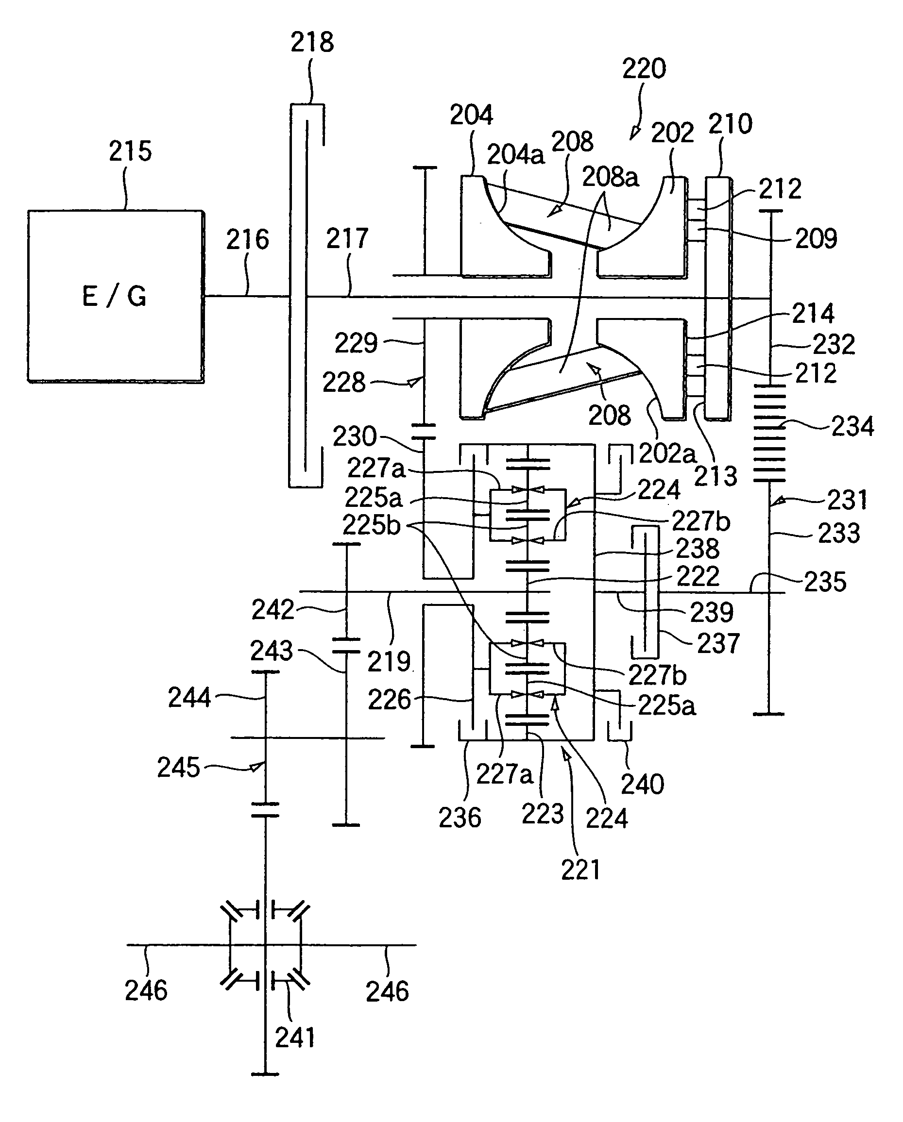
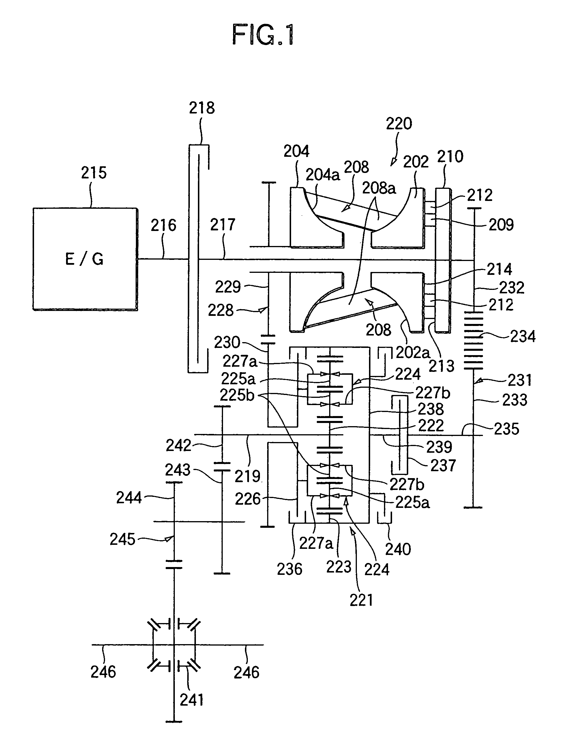
[0046]FIG. 1 shows the invention. A continuously variable transmission according to this embodiment is provided with an input shaft 217 connected to the crank shaft 216 of an engine 215 which is a drive source and rotatively driven by this engine 215. A starting clutch 218 is provided between the input side end portion (the left end portion as viewed in FIG. 1) of the input shaft 217 and the output side end portion (the right end portion as viewed in FIG. 1) of the crank shaft 216 in series with the crank shaft 216 and the input shaft 217. Accordingly, in the case of the present embodiment, the crank shaft 216 and the input shaft 217 are disposed concentrically with each other. In contrast, an output shaft 219 for taking out power based on the rotation of the input shaft 217 is disposed parallel to the input shaft 217. A single cavity-type toroidal type continuously variable transmission 220 is provided around the input shaft 217, and a planetary gear mechanism 221 is provided aroun...

second embodiment

[0070]Next, FIGS. 8 to 11 show the invention. This continuously variable transmission includes an input side rotating shaft (input shaft) 11b, an output shaft 29a, a toroidal type continuously variable transmission 19a, a planetary gear device 20a, a first power transmitting means 34a and a second power transmitting means 40a. The input side rotating shaft 11b of these members is connected to a drive source such as an unillustrated engine disposed on the left-hand side in FIG. 8, and is rotatively driven by this drive source.

[0071]The output shaft 29a is for taking out power based on the rotation of the input side rotating shaft 11b, and is connected to an unillustrated vehicle-wheel drive shaft through an unillustrated differential gear and the like.

[0072]The toroidal type continuously variable transmission 19a is of the double cavity type and is provided with three trunnions 7 and three power rollers 9 in each cavity, or six trunnions 7 and six power rollers 9 in total. To constru...


PUM


Abstract

A continuously variable transmission has: an input shaft, an output shaft, a toroidal type continuously variable transmission, and a planetary gear mechanism including a sun gear, a ring gear and a planetary gear. The power transmitted to first and second power transmission systems is made to converge to two gears of the planetary gear mechanism, and a remaining gear is coupled with the output shaft. A mode changeover device effects a changeover between, during forward movement, a first mode for a low speed side, which utilizes the first power transmission system and a second mode for a high speed side, which utilizes the first and second power transmission systems. Such changeover is effected by the operation of connecting and disconnecting a first mode clutch and a second mode clutch. The operation of effecting the changeover between the first mode and the second mode is effected in 0.2 to 1 second.

Description

BACKGROUND OF THE INVENTION[0001]1. Field of the Invention[0002]This invention relates to improvements in a continuously variable transmission incorporating therein a toroidal type continuously variable transmission utilized, for example, as a transmission for an automobile.[0003]2. Description of the Related Art[0004]U.S. Pat. No. 5,888,160 discloses a continuously variable transmission which includes an input shaft rotatively driven by a drive source, an output shaft for taking out power based on the rotation of this input shaft, a toroidal type continuously variable transmission having input and output discs and a power roller which are interposed between the input shaft and the output shaft, and a planetary gear mechanism.[0005]This continuously variable transmission has two modes for a low speed side and a high speed side during forward movement, wherein the mode for the low speed side utilizes a power transmission system routed through only the toroidal type continuously varia...

Claims


Application Information

Patent Timeline
IPC IPC(8): F16H37/02B60W10/04F16H41/04F16H37/08F16H61/04F16H61/08F16H61/664
CPCF16H37/086F16H61/04Y10T477/6937F16H2037/0886Y10T477/6217F16H61/664
Inventor MIYATA, SINJILIU, DAPING
Owner NSK LTD
Learn More