

Linear motor, and linear compressor using the same
a linear compressor and linear motor technology, applied in the direction of positive displacement liquid engine, piston pump, magnetic body, etc., can solve the problems of increasing cost, affecting the efficiency of linear compressors, and difficulty in enhancing efficiency
- Summary
- Abstract
- Description
- Claims
- Application Information
AI Technical Summary
Benefits of technology
Problems solved by technology
Method used
Image

Examples
exemplary embodiment 1
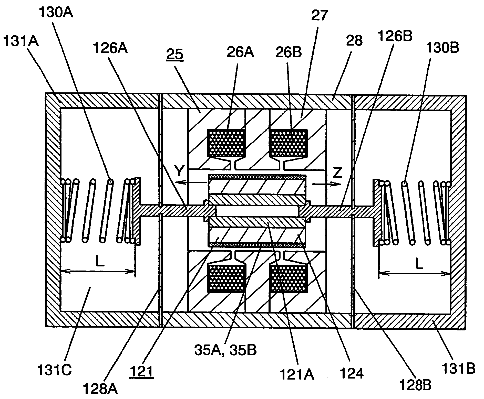
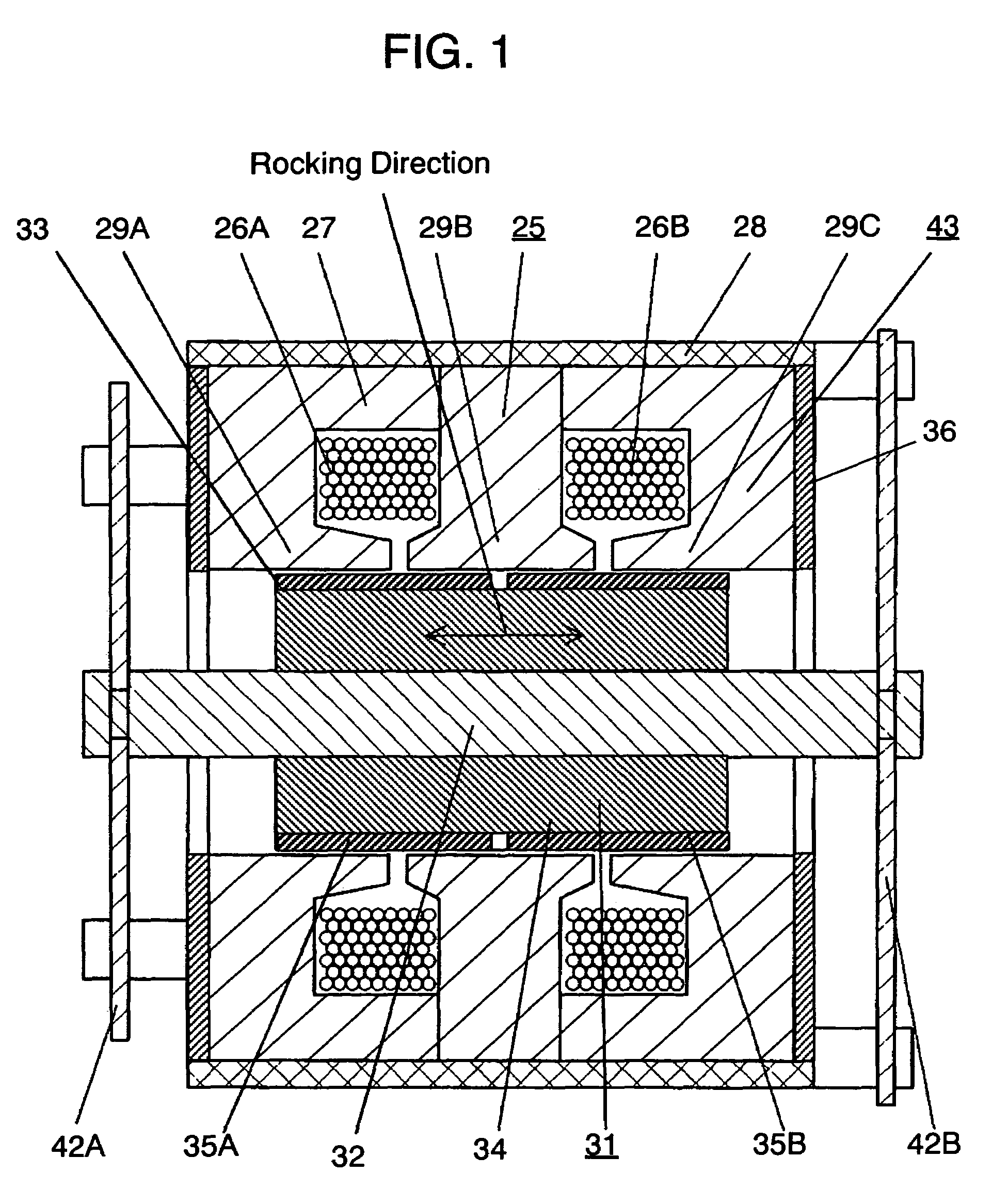
[0043]FIG. 1 is a sectional side elevation of a linear motor according to the first exemplary embodiment of the present invention. FIG. 2 is a schematic diagram showing the relative positions of planar springs, and perspectively shows a mover 31, a stator 25 and a planar spring 42B, from the side of a planar spring 42A in FIG. 3. FIG. 3 is an exploded perspective view showing the assembly of the linear motor, FIG. 4 is a schematic diagram showing the action principle of the linear motor, and FIG. 5 is a schematic diagram showing the directions in which the electric current of the linear motor flows.
[0044]The stator 25 of a generally cylindrical shape includes two magnet wires 26A and 26B wound in a ring shape, a stationary iron core 27, and a frame 28 supporting the outer circumference of the stationary iron core 27. The stationary iron core 27 houses the magnet wires 26A and 26B and forms three magnet poles 29A, 29B and 29C on its inner circumference.
[0045]The stationary iron core ...
exemplary embodiment 2
[0064]FIG. 6 is a sectional side elevation of a linear compressor according to the second exemplary embodiment of the present invention, and FIG. 7 is a horizontal section of FIG. 6. A closed casing (as will be called the “case”) 41 houses a compressor body 53 having the linear motor 43.
[0065]In a cylinder 51 connected to the stator 25 of the linear motor 43, there is reciprocally inserted a piston 52, which is connected to the mover 31 of the linear motor 43. To the end face of the cylinder 51, there are attached a cylinder head 54 and a suction muffler 55. The cylinder head 54, the suction muffler 55, the cylinder 51, the stator 25 and so on form a stationary unit 57.
[0066]A moving unit 58 is composed of the piston 52, the mover 31 and so on. The piston 52 is attached to the distal end of the shaft 32 of the mover 31, and the shaft 32 and the piston 52 are rotatably connected to each other through a ball joint 61. The planar springs 42A and 42B are individually attached at their c...
exemplary embodiment 3
[0072]FIG. 8 is a sectional view of a linear compressor according to the third exemplary embodiment 3 of the present invention. A piston 71 and the mover 31 are connected to each other through a compliance rod (as will be called the “rod”) 72. The remaining constructions are similar to those of the second embodiment.
[0073]The rod 72 is constructed of such a radially small rod-shaped elastic member as has transverse flexibility and elasticity while retaining a rigidity for supporting the load in the axial direction. Specifically, the rod 72 is made of a metallic material having an elasticity and a rigidity, such as stainless steel or spring steel. Namely, the rod 72 can move in parallel with the axis of the piston 71 and is flexible in the rotating direction. Even with a small deviation between the shaft 32 of the mover 31 and the axis of the cylinder 51, therefore, the wrench between the piston 71 and the cylinder 51 is prevented so as to prevent the friction and the wear.
PUM
| Property | Measurement | Unit |
|---|---|---|
| electric currents | aaaaa | aaaaa |
| attaching angle | aaaaa | aaaaa |
| attaching angles | aaaaa | aaaaa |
Abstract
Description
Claims
Application Information