Techniques to test signal propagation media

Inactive Publication Date: 2006-07-18
MICRON TECH INC
View PDF5 Cites 2 Cited by
  • Summary
  • Abstract
  • Description
  • Claims
  • Application Information

AI Technical Summary

Problems solved by technology

One drawback with this technique is that linear time-invariant filters typically used to filter the reflected signal cannot adequately filter a reflected signal with applied gain that increases over time.
However, such high gain technique may saturate portions of the re

Method used


Image

  • Techniques to test signal propagation media
  • Techniques to test signal propagation media
  • Techniques to test signal propagation media

Examples


Embodiment Construction

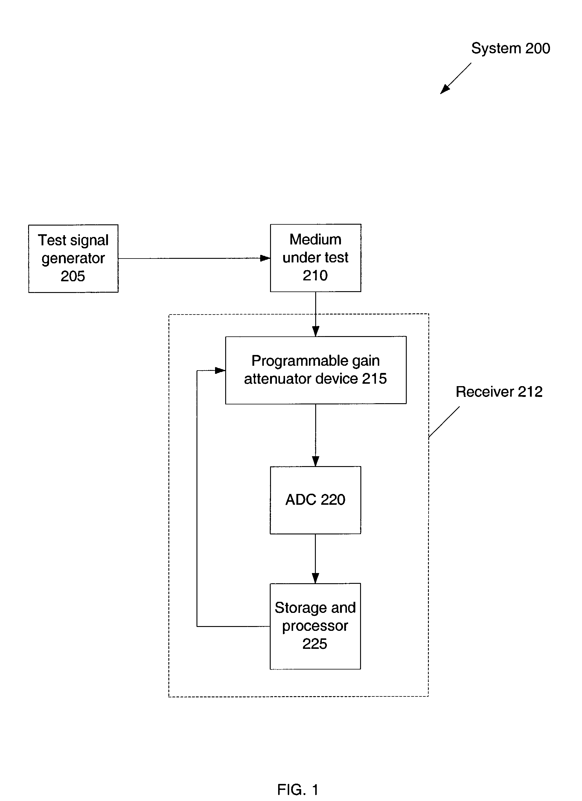
[0009]FIG. 1 depicts a system 200 that can be used in an embodiment of the present invention. System 200 may include: test signal generator 205, medium under test (MUT) 210, and receiver 212. For example, test signal generator 205 may output test signals to the MUT 210. The test signal may be an impulse signal. MUT 210 may be implemented as a twisted pair copper cable, coaxial cable, power transmission line, fiber optical cable, or any signal propagation medium. MUT 210 may reflect a test signal transmitted by test signal generator 205 to receiver 212. For example, MUT 210 may be configured in open or shorted loop manners. Test signal generator 205 and receiver 212 may be implemented as hardwired logic, software stored by a memory device and executed by a microprocessor, firmware, an application specific integrated circuit (ASIC), and / or a field programmable gate array (FPGA).

[0010]Receiver 212 may provide characteristics of MUT 210 based on test signals transmitted through MUT 210 ...


PUM


Abstract

Briefly, techniques that may be used to provide characteristics of a signal propagation medium. Based on test signals transmitted into the medium, the techniques may be used to construct a mosaic waveform with multiple time segments. Each time segment may be based on a gain enhanced received reflected signal and each time segment may have an applied gain that is at a highest level without causing saturation. The techniques may further remove unwanted bridge tap reflection.

Description

FIELD[0001]The subject matter disclosed herein generally relates to techniques to test signal propagation media.DESCRIPTION OF RELATED ART[0002]Signal propagation media may be used to transmit signals in a communications system. Examples of signal propagation media include a twisted copper pair cable, fiber optic cable, and coaxial cable. One manner to test a signal propagation medium is to apply an impulse test signal and to analyze a reflected signal resulting from the test signal.[0003]There are several well-known techniques to measure the characteristics of a signal propagation medium. One technique is known as ultra sound imaging whereby the gain applied to the reflected signal is increased over time. One drawback with this technique is that linear time-invariant filters typically used to filter the reflected signal cannot adequately filter a reflected signal with applied gain that increases over time. Another technique involves applying a constant high gain to the reflected si...

Claims


Application Information

Patent Timeline
IPC IPC(8): G01R31/11G01R27/04G01R27/32G01R31/02H04B3/00H04B3/46H04M1/74
CPCH04M1/74H04B3/46G01R31/11G01R31/021G01R31/58
Inventor HAN, CHUNMING
Owner MICRON TECH INC
Why Eureka
Try Eureka