Devices and methods for dynamic dispersion compensation

a dynamic dispersion and optical signal technology, applied in multiplex communication, instruments, cladded optical fibres, etc., can solve the problems of loss of signal fidelity, increased bit error rate, and increased insertion loss, so as to avoid high insertion loss and react quickly

Inactive Publication Date: 2006-07-18
CORNING INC
View PDF17 Cites 4 Cited by
  • Summary
  • Abstract
  • Description
  • Claims
  • Application Information

AI Technical Summary

Benefits of technology

[0011]The devices and methods of the present invention result in a number of advantages over prior art devices and methods. For example, the present invention provides a dispersion compensating device that can provide broadband compensation of a wavelength division multiplexed optical signal. The dispersion compensating devices, systems and methods of the present invention can effectively compress pulses having a wide range of chirps, thereby providing compensation for a wide range of residual dispersion values. The dispersion compensating devices, systems and methods of the present invention provide compression of pulses having a wide dynamic range of pulse widths and peak powers. The devices are fiber-based, and therefore do not suffer from high insertion losses associated with coupling energy into planar or micro-optic devices. The devices, systems and methods of the present invention rely on a nonlinear effect to provide dynamic compensation; as such, the device will react quickly to changes in the chirp of the optical signal. The dispersion compensating devices of the present invention can also provide gain to an optical signal. The devices and methods of the present invention are especially useful for compensation of residual dispersion in long-distance 10 Gb / s and in 40 Gb / s optical communications systems.

Problems solved by technology

As the bit rates of optical communications systems increase, the deleterious effects of dispersion in the optical fibers used in long-distance transmission become increasingly important.
This temporal spreading can cause loss of signal fidelity and an increase in bit error rate.
While such conventional methods are relatively simple to implement, they are limited in that they are passive; the dispersion compensation properties of such passive dispersion compensation devices are determined by the length and dispersion properties of the dispersion compensating fiber.
If the chirp of the incoming optical signal is substantially different than that for which the device was designed, the device will be ineffective at providing an essentially chirp-free optical signal.
Such devices are also generally unable to remove all of the chirp of the optical signal, imposing a residual dispersion on the transmission link.
Residual dispersion is especially damaging in long-distance (e.g. >1000 km) 10 Gb / s systems as well as in 40 Gb / s systems.
Conventional grating-based devices and planar waveguide-based devices provide controllable dispersion compensation only over a relatively narrow band of wavelengths, and are very expensive to produce.
While these devices can provide broadband compensation, they suffer from high excess loss and low reliability.

Method used


Image

  • Devices and methods for dynamic dispersion compensation
  • Devices and methods for dynamic dispersion compensation
  • Devices and methods for dynamic dispersion compensation

Examples


example 1

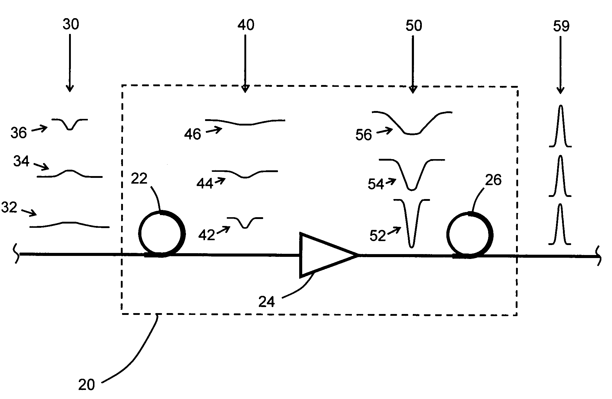
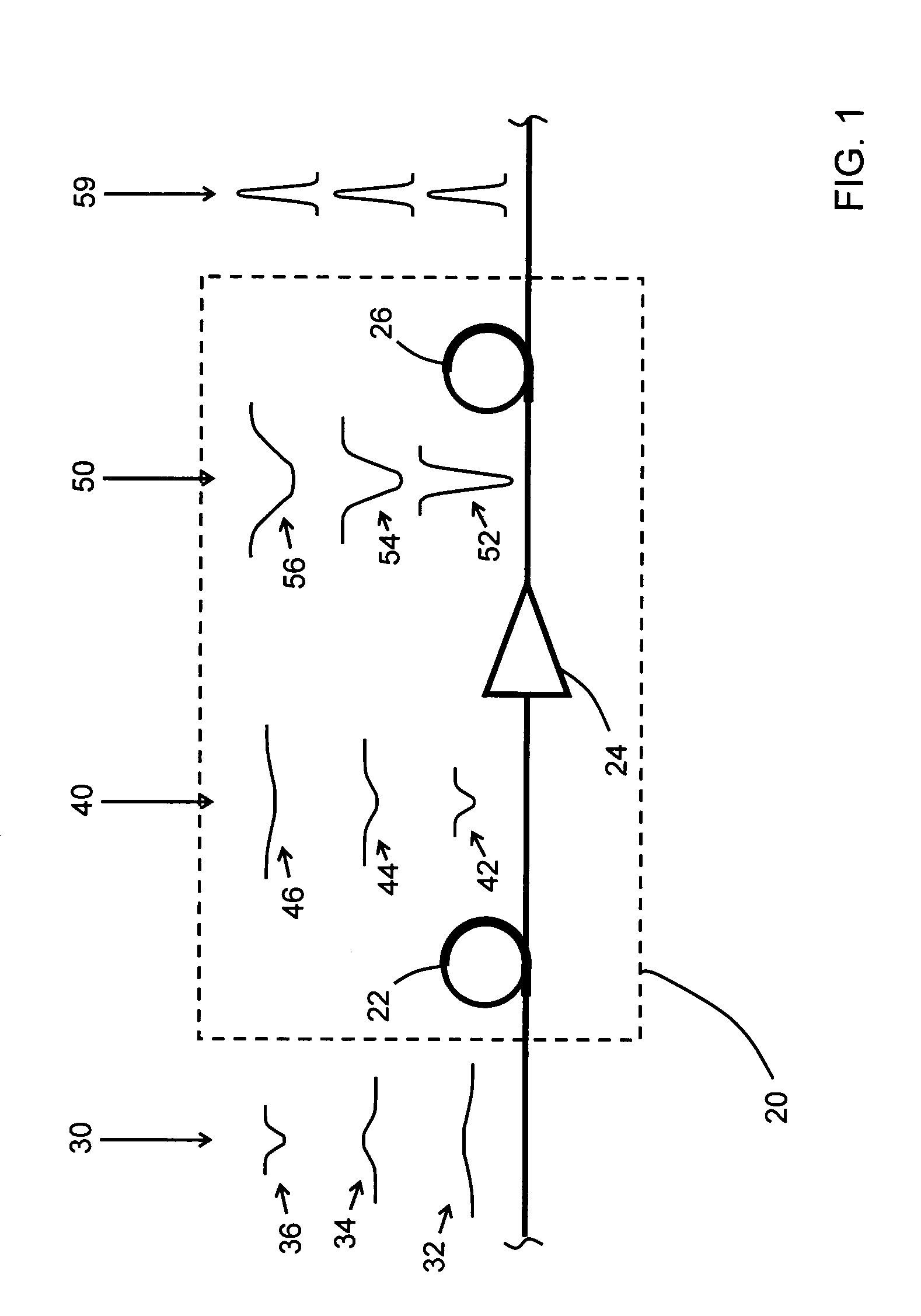
[0049]A dispersion compensating device including a negative dispersion fiber, an amplifying device, and a nonlinear positive dispersion fiber was constructed as shown in FIG. 1. The negative dispersion fiber was a flat slope dispersion compensating single mode fiber of a length sufficient to impose a dispersion of −440 ps / nm. The amplifying device included an erbium-doped fiber amplifier capable of 100 mW output along with a variable optical attenuator to control the gain of the amplifier. The nonlinear positive dispersion fiber had a dispersion of −22 ps / nm / km at a wavelength of 1550 nm, a propagation loss of about 0.45 dB / km, an effective area of 38 μm2, and a length of 20 km.

[0050]An optical transmission system was coupled to the input of the negative dispersion fiber. The optical network system included 12 optical nodes (e.g. 4 optical cross-connects and 7 optical add-drop multiplexers) with 11 spans of LEAF® 100 km in length connecting the nodes. Each span of LEAF® was compensa...

example 2

[0054]The effect of Raman pumping on the devices of the present invention was investigated using the experimental setup of FIG. 11. A negatively chirped input signal was generated by gain switching a DFB laser diode 112 at 10 GHz. The center wavelength of the signal was 1546.72 nm, and the spectral bandwidth and duration of the pulses were 0.32 nm and 21.7 ps, respectively. The estimated chirp parameter of the pulses was C=1.67. The gain of the laser diode was adjusted to provide a desired signal power. It is noted that the high power, negatively chirped input signal simulated the output of the amplifying device in the devices of the present invention.

[0055]The negatively chirped input signal was coupled into a 5773 m length of nonlinear positive dispersion fiber 114 having a loss at 1450 nm of 0.766 dB / km, a loss at 1550 nm of 0.448 dB / km, a mode field diameter at 1550 nm of 4.416 μm, a dispersion at 1550 nm of 3.961 ps / nm / km, a dispersion slope at 1550 nm of 0.0486 ps / nm2 / km, and ...


PUM


Abstract

The present invention provides devices and methods for dispersion compensation. According to one embodiment of the invention, a dispersion compensating device includes a negative dispersion fiber having an input configured to receive the optical signal, the negative dispersion fiber having a length and dispersion sufficient to remove any positive chirp from each wavelength channel of the optical signal, thereby outputting a negatively chirped optical signal; an amplifying device configured to amplify the negatively chirped optical signal; and a nonlinear positive dispersion fiber configured to receive the negatively chirped optical signal. The devices of the present invention provide broadband compensation for a systems having a wide range of variable residual dispersions.

Description

CROSS-REFERENCE TO RELATED APPLICATIONS[0001]This application claims the benefit of priority of U.S. Provisional Application Ser. No. 60 / 418,080 filed on Oct. 11, 2002, which is incorporated by reference herein in its entirety.BACKGROUND OF THE INVENTION[0002]1. Field of the Invention[0003]The present invention relates generally to optical communications, and more specifically to devices and methods providing dispersion compensation of an optical signal.[0004]2. Technical Background[0005]As the bit rates of optical communications systems increase, the deleterious effects of dispersion in the optical fibers used in long-distance transmission become increasingly important. Dispersion causes an optical pulse to spread out in time; the longer wavelength components of the pulse travel along the fiber at a different rate than do the shorter wavelength components of the pulse. Typically, long-distance transmission fibers (e.g. LEAF®, available from Corning Incorporated of Corning, N.Y.) ha...

Claims


Application Information

Patent Timeline
Patent Type & Authority Patents(United States)
IPC IPC(8): G02B6/02H01S3/00G02B6/00
CPCG02B6/29377G02B6/29394H01S3/06754H01S3/0057H01S3/0064H01S3/302H01S3/06725H01S3/06729H01S3/06758H01S3/0078
Inventor KOROLEV, ANDREY ELABILLOY, DOMINIQUENOLAN, DANIEL ASOLOVJEV, VASILIY
Owner CORNING INC
Why Eureka
Try Eureka