Devices and methods for dynamic dispersion compensation

Inactive Publication Date: 2006-06-27
CORNING INC
View PDF19 Cites 24 Cited by
  • Summary
  • Abstract
  • Description
  • Claims
  • Application Information

AI Technical Summary

Benefits of technology

[0012]The devices and methods of the present invention result in a number of advantages over prior art devices and methods. For example, the present invention provides a dispersion compensating device that can provide broadband compensation of a wavelength division multiplexed optical signal. The dispersion compensating devices, systems and methods of the present invention can effectively compress pulses having a wide range of chirps, thereby providing compensation for a wide range of residual dispersion values. The dispersion compensating devices, systems and methods of the present invention provide compression of pulses having a wide dynamic range of pulse widths and peak powers. The devices are fiber-based, and therefore do not suffer from high insertion losses associated with coupling energy into planar or micro-optic devices. The devices, systems and methods of the present invention rely on a nonlinear effect to provide dynamic compensation; as such, the device will react quickly to changes in the chirp of the optical signal. The dispersion compensating devices of the present invention can also provide gain to an optical signal. The devices and methods of the present invention are especially useful for compensation of residual dispersion in long-distance 10 Gb / s and in 40 Gb / s RZ (return to zero) optical communications systems.
[0013]Another advantage of the dispersion compensation device of the present invention is that it is dynamic over a broad spectral band. That is, it is capable of simultaneously compensating for variable amounts of chromatic dispersion in several different spectral channels of the WDM system covering a spectral band with a width of at least 30 nm.

Problems solved by technology

As the bit rates of optical communications systems increase, the deleterious effects of dispersion in the optical fibers used in long-distance transmission become increasingly important.
This temporal spreading can cause loss of signal fidelity and an increase in bit error rate.
While such conventional methods are relatively simple to implement, they are limited in that they are passive; the dispersion compensation properties of such passive dispersion compensation devices are determined by the length and dispersion properties of the dispersion compensating fiber.
If the chirp of the incoming optical signal is substantially different than that for which the device was designed, the device will be ineffective at providing an essentially chirp-free optical signal.
Such devices are also generally unable to remove all of the chirp of the optical signal, imposing a residual dispersion on the transmission link.
Residual dispersion is especially damaging in long-distance (e.g. >1000 km) 10 Gb / s systems as well as in 40 Gb / s systems.
Conventional grating-based devices and planar waveguide-based devices provide controllable dispersion compensation only over a relatively narrow band of wavelengths, and are very expensive to produce.
While these devices can provide broadband compensation, they suffer from high excess loss and low reliability.

Method used


Image

  • Devices and methods for dynamic dispersion compensation
  • Devices and methods for dynamic dispersion compensation
  • Devices and methods for dynamic dispersion compensation

Examples


example 1

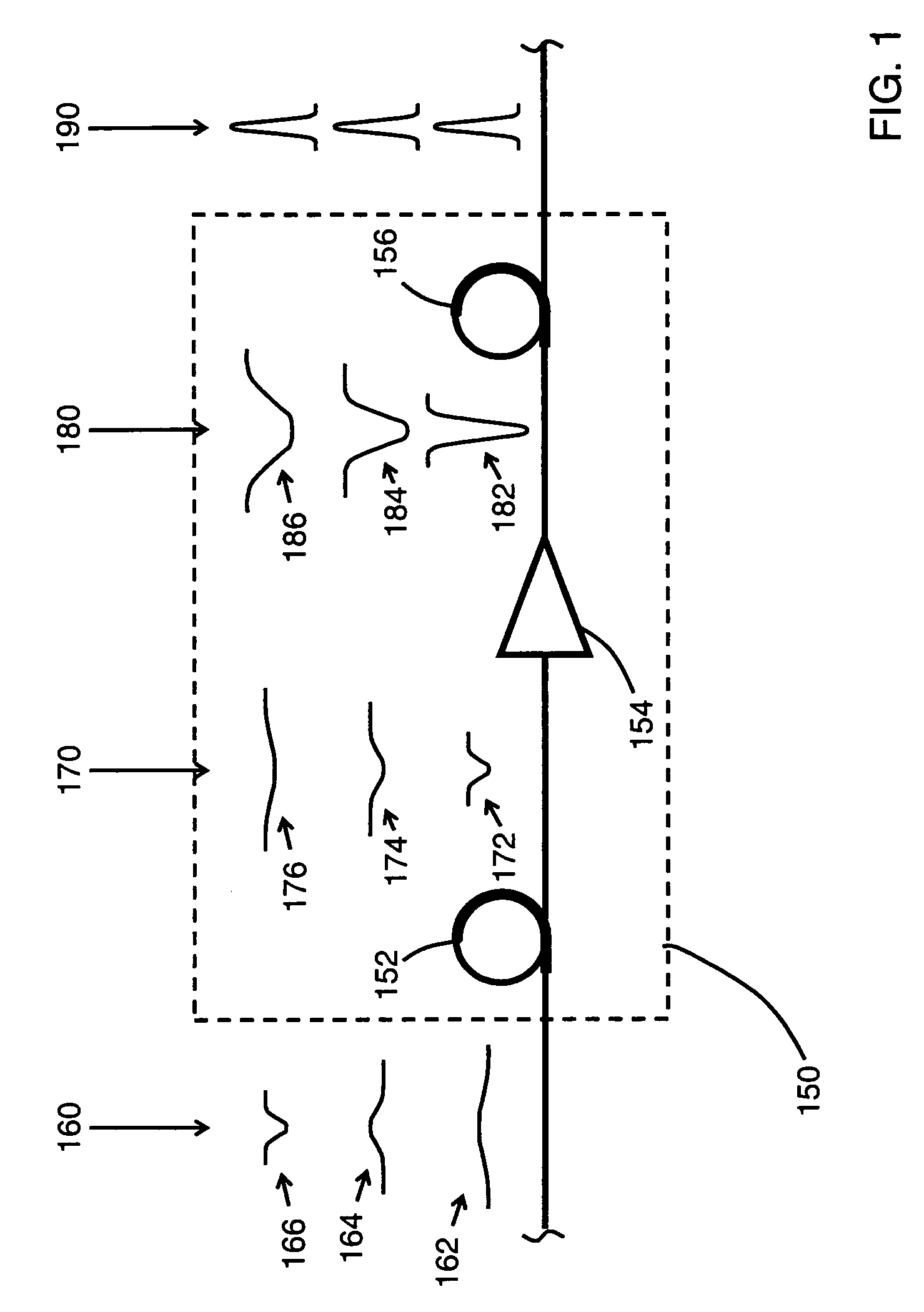
[0099]A dispersion compensating device including a negative dispersion fiber, an amplifying device, and a nonlinear positive dispersion fiber was constructed as shown in FIG. 17. The negative dispersion fiber 340 was a dispersion compensating fiber with a dispersion of −88.9 ps / nm / km, giving a total dispersion of −42 ps / nm at a wavelength of 1550 nm and a length of 600 meters. The amplifying device 342 was an erbium doped fiber amplifier capable of providing up to 30 dB gain. A variable optical attenuator 344 was coupled to the output of erbium doped fiber amplifier to provide fine control of the amplified pulse power. Nonlinear positive dispersion fiber 346 was coupled to variable optical attenuator 324. Nonlinear positive dispersion fiber 346 was 5.773 km long and had the following properties:

[0100]

Loss at 1450 nm0.766dB / kmLoss at 1550 nm0.448dB / kmMode field diameter at 1550 nm4.416μmDispersion at 1550 nm3.961ps / nm / kmDispersion slope at 1550 nm0.0486ps / nm2 / kmSingle mode cutoff1129...

example 2

[0103]The nonlinear positive dispersion fiber 346 of the device of Example 1 was replaced with 10 km of a nonlinear positive dispersion fiber having the following properties:

[0104]

Loss at 1450 nm2.17dB / kmLoss at 1550 nm0.69dB / kmMode field diameter at 1550 nm4.478μmDispersion at 1550 nm14.5ps / nm / kmDispersion slope at 1550 nm0.0547ps / nm2 / kmSingle mode cutoff1486.82nm

The nonlinear positive dispersion fiber had a total dispersion of 145 ps / nm at 1550 nm. The same signal as in Example 1 was used. The Raman pump power was 327 mW.

[0105]FIGS. 21 and 22 show pulse width and dispersion for various levels of amplification. About 38 ps, or about 120 ps / nm dispersion of the pulses is compensated by the device. The threshold power for achieving nearly total compensation was about 40 mW; this power could be reduced by using a nonlinear positive dispersion fiber having a lower loss. FIG. 23 shows the spectral and waveform details of the pulses at signal powers of 5.9 mW, 18.7 mW, and 47.2 mW. Only ...

example 3

[0106]In order to further increase the dynamic compensation range, the nonlinear positive dispersion fiber 346 of the device of Example 2 was replaced with 15 km of a nonlinear positive dispersion fiber having the following properties:

[0107]

Loss at 1450 nm0.809dB / kmLoss at 1550 nm0.449dB / kmMode field diameter at 1550 nm5.0939μmDispersion at 1550 nm17.38ps / nm / kmDispersion slope at 1550 nm0.0526ps / nm2 / kmSingle mode cutoff1416.42nm

The nonlinear positive dispersion fiber had a total dispersion of 260.7 ps / nm at 1550 nm. The same 10 Gb / s signal as in Example 2 was used. The Raman pump power was 300 mW.

[0108]FIGS. 24 and 25 show pulse width and dispersion as a function of pulse power. At low powers, the high dispersion of the nonlinear positive dispersion fiber imposed a large positive dispersion (˜250 ps / nm) on the signal. At a pulse power of about 48 mW, nearly complete compensation of dispersion was achieved. Pulsewidth and dispersion remained essentially constant at pulse powers rangi...


PUM


Abstract

The present invention provides devices and methods for dynamic dispersion compensation. According to one embodiment of the invention, a dispersion compensating device includes a negative dispersion fiber having an input configured to receive the optical signal, the negative dispersion fiber having a length and dispersion sufficient to remove any positive chirp from each wavelength channel of the optical signal, thereby outputting a negatively chirped optical signal; an amplifying device configured to amplify the negatively chirped optical signal; and a nonlinear positive dispersion fiber configured to receive the negatively chirped optical signal. The devices of the present invention provide broadband compensation for systems having a wide range of variable residual dispersions.

Description

[0001]This application claims the benefit of priority under 35 U.S.C. § 119(e) of U.S. Provisional Application Ser. No. U.S. 60 / 447,174 filed on U.S. Parent Provisional Application Filing Feb. 13, 2003 the content of which is relied upon and incorporated herein by reference in its entirety.BACKGROUND OF THE INVENTION[0002]1. Field of the Invention[0003]The present invention relates generally to optical communications, and more specifically to devices and methods providing dispersion compensation of an optical signal.[0004]2. Technical Background[0005]As the bit rates of optical communications systems increase, the deleterious effects of dispersion in the optical fibers used in long-distance transmission become increasingly important. Dispersion causes an optical pulse to spread out in time; the longer wavelength components of the pulse travel along the fiber at a different rate than do the shorter wavelength components of the pulse. Typically, long-distance transmission fibers (e.g....

Claims


Application Information

Patent Timeline
IPC IPC(8): H04B10/12H04B10/18
CPCH04B10/2525
Inventor KOROLEV, ANDREY E.KUKSENKOV, DMITRI V.LI, SHENPINGNOLAN, DANIEL A.SAUER, MICHAELSYSOLIATIN, ALEXEJ
Owner CORNING INC
Why Eureka
Try Eureka