Communication system transmitter or receiver module having integrated radio frequency circuitry directly coupled to antenna element

Active Publication Date: 2006-07-18
LUCENT TECH INC
View PDF6 Cites 28 Cited by
  • Summary
  • Abstract
  • Description
  • Claims
  • Application Information

AI Technical Summary

Benefits of technology

[0013]In accordance with a further aspect of the invention, each of at least a subset of the plurality of modules of the transceiver may be configured to provide adjustable amplitude and phase, independent of one or more of the other modules, for a corresponding transmit or receive signal associated therewith. Thus, the invention allows signal amplitude and phase to be varied on a module-by-module basis, so as to facilitate the provision of electronic antenna steering or other similar functionality.
[0014]Advantageously, by appropriate selection of the number of transmitter modules, the need for conventional high power amplification using discrete power transistors can be eliminated. The transmitter modules can be readily configured such that their outp

Problems solved by technology

Moreover, the transmitter modules can be configured such that their output signal energies interfere destructively in the near field, thereby

Method used


Image

  • Communication system transmitter or receiver module having integrated radio frequency circuitry directly coupled to antenna element
  • Communication system transmitter or receiver module having integrated radio frequency circuitry directly coupled to antenna element
  • Communication system transmitter or receiver module having integrated radio frequency circuitry directly coupled to antenna element

Examples


Embodiment Construction

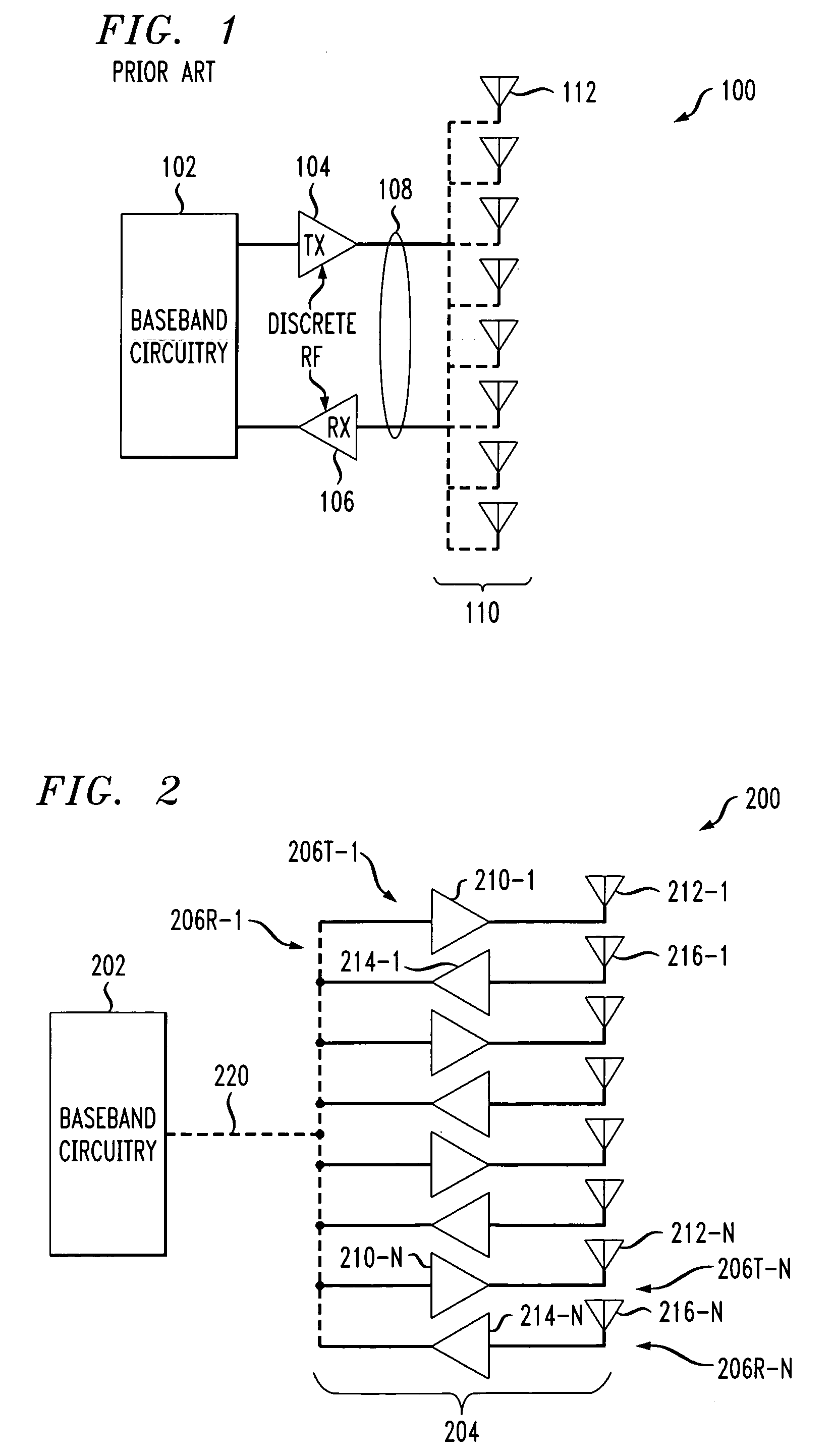
[0026]The present invention will be illustrated herein in conjunction with example transmitter and receiver modules each having integrated radio frequency (RF) circuitry directly coupled to an antenna element. It is to be appreciated, however, that the invention does not require the particular module and circuitry configurations of the illustrative embodiments. The invention is more generally suitable for use in any communication system application in which it is desirable to provide improvements such as reduced device size, cost and power consumption, as well as enhanced reconfiguration flexibility. By way of example, the invention can be used in applications such as wireless cellular system base stations, in stations or access points associated with wireless local area networks such as IEEE 802.11 networks, radar systems, as well as numerous other applications.

[0027]FIG. 2 shows a wireless cellular system base station 200 in accordance with an illustrative embodiment of the invent...


PUM


Abstract

A radio frequency (RF) module for use in a communication device of a communication system includes integrated RF circuitry comprising at least one of a transmitter and a receiver, and an antenna element having at least one portion thereof arranged substantially adjacent to and operatively coupled to the integrated RF circuitry. For example, the antenna element may include at least first and second portions having opposing edges arranged immediately adjacent respective first and second sides of the integrated RF circuitry. A plurality of the modules can be used to implement a transceiver in a communication system base station or other communication device.

Description

FIELD OF THE INVENTION[0001]The present invention relates generally to communication systems, and more particularly to transmitter or receiver circuitry and associated antenna circuitry for use in such systems.BACKGROUND OF THE INVENTION[0002]Conventional arrangements of transceiver circuitry in a wireless cellular system base station or other similar communication system application typically include receiver and transmitter devices implemented at least in part using radio frequency (RF) components that are discrete rather than integrated. Such devices are typically located remotely from the corresponding antenna circuitry, and coupled thereto via coaxial cable or other similar connection mechanism. For example, a single base station transmitter including one or more power amplifiers may be coupled via coax to antenna circuitry comprising multiple antenna elements. Each of the multiple antenna elements may be associated with a different directional antenna or antenna sector of the ...

Claims


Application Information

Patent Timeline
IPC IPC(8): H04M1/00H01Q21/00H01Q23/00H04B1/04
CPCH01Q21/00H04B1/0458H01Q23/00H01Q1/525
Inventor AYTUR, TURGUT SEFKETBELK, NATHAN R.
Owner LUCENT TECH INC
Why Eureka
Try Eureka