Method of producing tissue by placing a molding support within a body cavity

Inactive Publication Date: 2008-10-30
THE UNIV OF QUEENSLAND
View PDF19 Cites 0 Cited by
  • Summary
  • Abstract
  • Description
  • Claims
  • Application Information

AI Technical Summary

Benefits of technology

[0021]Still another aspect of the present invention provides a prosthetic device which facilitates the provision of a foreign body such as a moulding support to a body cavity. Generally, although not exclusively, the prosthetic device comprises an elongated tubular member adapted to be inserted into a body cavity. The elongated tubular member is further adapted to receive an inner elongated memb

Problems solved by technology

Atherosclerosis is responsible for a high rate of mortality and an even higher rate of long term physical impairment of subjects affected by this disease.
However, while the mammary artery seldom develops atherosclerosis, it may not always be the proper size or length, and saphenous vein may have varicose degenerative alterations that can lead to aneurysm formation when transplanted to a high pressure arterial site.
Furthermore, the non-thrombogenic surface of endothelial cells of saphenous veins is often damaged during graft preparation.
Venous and arterial allografts have also been tried but have generally been abandoned clinically as they show a high incidence of rejection, deterioration and complications.
Similarly, the use of dialdehyde starch tanned bovine xenografts has been generally abandoned due to a high incidence of aneurysm formation and poor resistance to infection.
Nylon was found to lose most of its tensile strength after a brief period of implantation leading to aneurysmal dilation and graft rupture.
Although both polyethylene terephthalate (DACRON) and polytetrafluoroethylene (TEFLON) fabric grafts perform reasonably satisfactorily in high flow, low resistance conditions such as in the aorta, iliac and proximal femoral arteries, neither of these two materials is satisfactory for small caliber arterial reconstructions.
Such grafts are compounded by graft failures from stenosis at the anastomic sites and excessive intimal hyperplasia.
These complications are associated with graft thrombogenicity, poor healing and lack of co

Method used


Image

  • Method of producing tissue by placing a molding support within a body cavity
  • Method of producing tissue by placing a molding support within a body cavity
  • Method of producing tissue by placing a molding support within a body cavity

Examples


example 1

Creation of an Artificial Blood Vessel

[0113]The first step in creating an artificial blood vessel was to determine an appropriate implant material which would:

[0114](i) initiate granulation tissue development;

[0115](ii) be covered by mesothelium;

[0116](iii) form a tube-like structure;

[0117](iv) be of variable diameter and length;

[0118](v) not attach to omentum / mesentery in the peritoneal cavity; and

[0119](vi) allow its own easy removal from the granulation tissue.

[0120]The second step was to determine its optimal time for harvest.

[0121]a) Selection of Appropriate Material as an Arterial Template

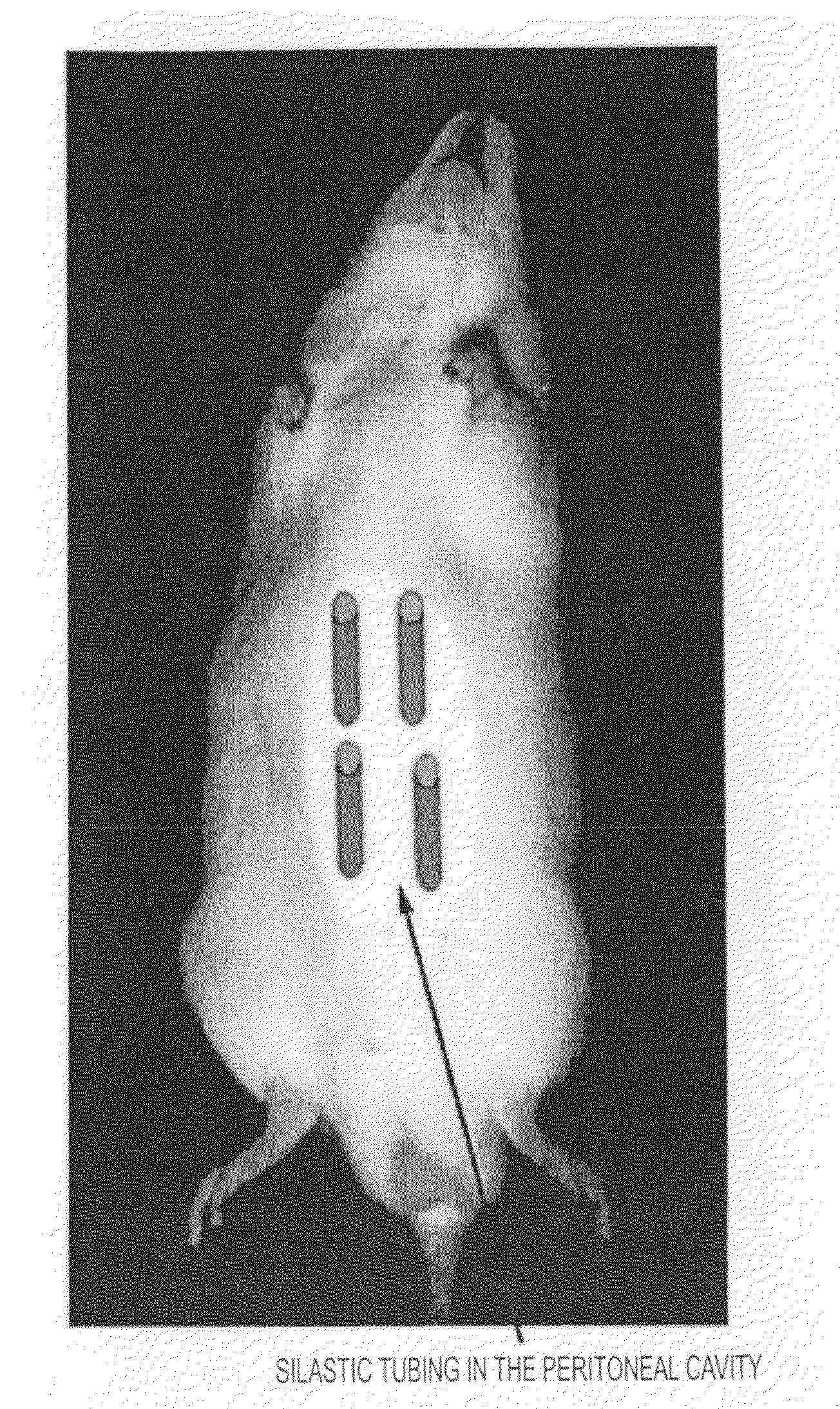
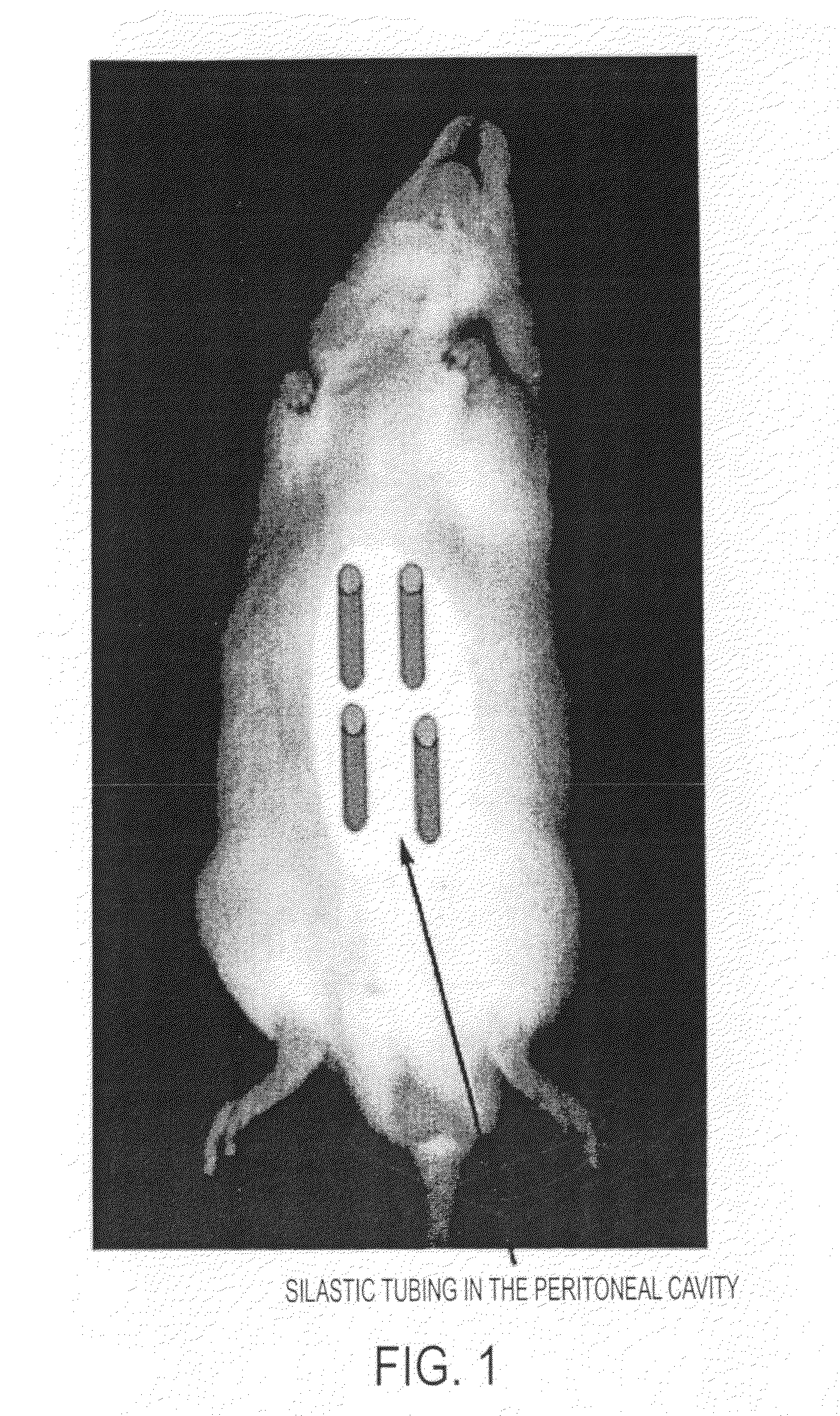
[0122]Twenty male adult Wistar rats were anaesthetized with 2.5% v / v (O2) halothane. A 20 mm incision was made in the shaved abdominal wall and a variety of objects—plastic silastic tubing (inner diameter range from 0.5-5 mm), glass rod, expanded polytetrafluoroethylene (ePTFE) graft (inner diameter 5 mm) and polyethylene terephthalate (DACRON) graft (inner diameter 6 mm)—inserted inside the ...

example 2

Myofibroblast Tubes can be Grown to Different Lengths and in Different Species

[0132]Having established that silastic tubing is a suitable mould to produce a myofibroblast tube, that tubes of different diameter (0.5 to 5 mm) could be produced, and that 2 weeks is the optimal period for their development within the peritoneal cavity, the inventors next determined whether artificial arteries could be produced in a species other than the rat, and whether these vessels could be longer.

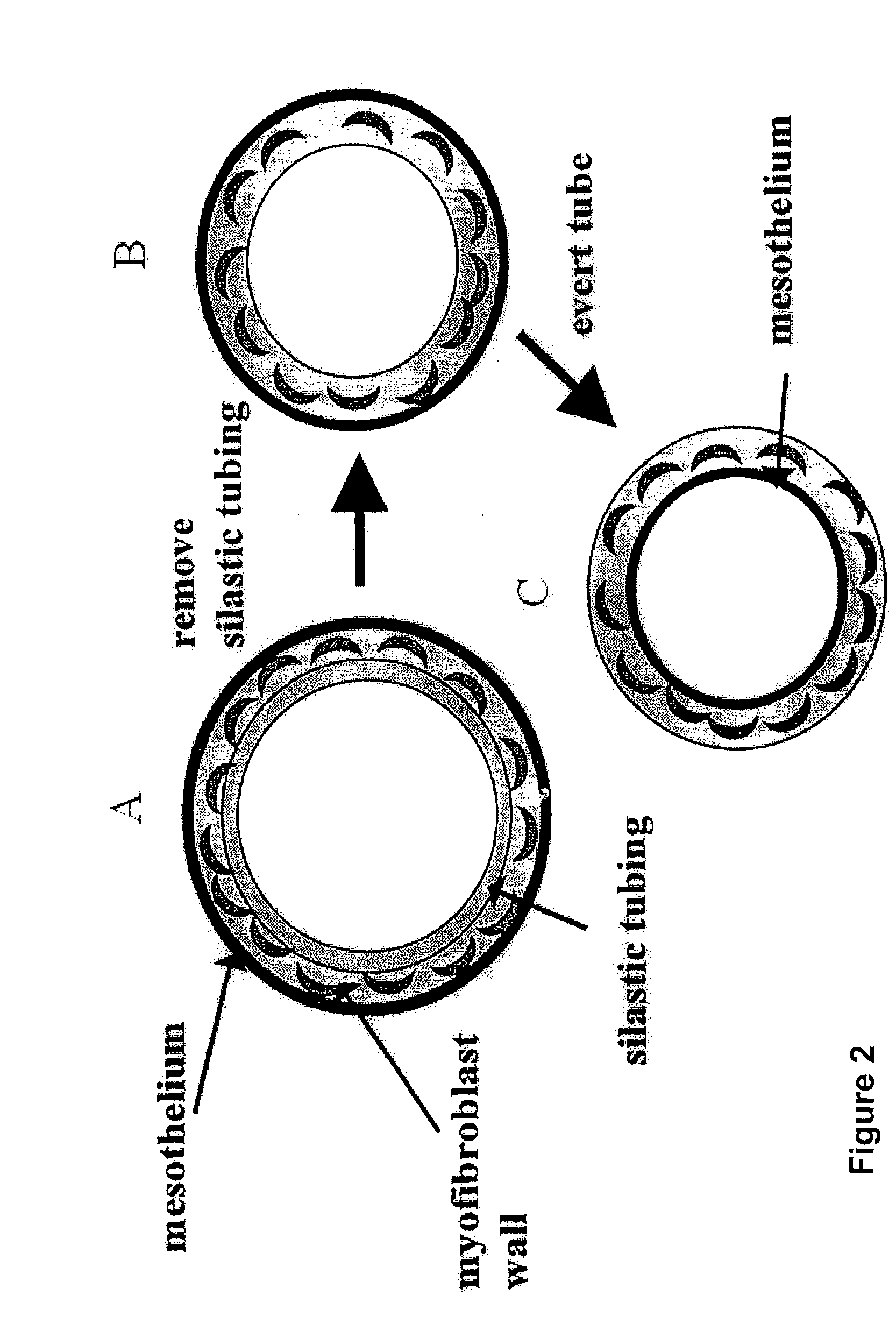
[0133]Four pieces of silastic tubing with outer diameter of 3 mm and length 10 mm (rat) and 5 mm by 20 mm (rabbit) were placed inside each animal. Five male Wistar rats and five male New Zealand White Cross rabbits were used. Two weeks after graft placement, animals were sacrificed. The silastic tubing was carefully removed and the tube of tissue gently everted such that the mesothelial layer now lined the inside of the freed myofibroblast tube. Segments of the four myofibroblast tubes (free-floating) from ...

example 3

Macrophages are the Source of Myofibroblasts / Smooth Muscle in the Peritoneal Tubes of Tissue

[0139]a) In Vitro Studies

[0140]Cultures of macrophage cell lines (RAW 264 and J774) were grown in Dulbecco's Modified Essential Medium (Gibco) and 10% v / v foetal calf serum at 371 C in 6% v / v CO2 humidified incubators. At sub-confluency, 25 U / ml of γ-interferon (Holan Biotechnology) was added to the macrophages and incubated for 16 hours. This cytokine caused de novo expression of SM α-actin proteins in both the RAW 264 (16%) and J774 (13.5%) macrophages, as measured by Western blotting (Hartig et al, 1997 supra) [FIG. 7].

[0141]This experiment indicates that γ-interferon induces pure populations of macrophages to express the smooth muscle contractile protein α-actin, which is not normally expressed by these cells. Thus, it may be possible for macrophages to be a source of cells containing contractile protein under certain inflammatory conditions.

[0142](b) In Vivo Studies

[0143]Definitive proof...


PUM


Abstract

A method of producing a tissue includes placing a molding support within a body cavity for a time and under conditions sufficient for non-vascularized tissue comprising myofibroblasts to form on the molding support. In some embodiments, the tissue produced by this method is particularly useful as vascular tissue for the treatment or prophylaxis of diseased or damaged blood vessels such as in atherosclerosis.

Description

CROSS-REFERENCE TO RELATED APPLICATIONS[0001]This application is a continuation application of U.S. Ser. No. 10 / 628,308, filed Jul. 29, 2003, which is a continuation-in-part application of U.S. Ser. No. 09 / 763,359, filed May 15, 2001, now U.S. Pat. No. 6,626,823, which is a 371 of PCT / AU1999 / 00670, filed Aug. 20, 1999, the disclosures of which are hereby incorporated by reference.FIELD OF THE INVENTION[0002]The present invention relates generally to tissue implant material for use in grafting procedures. More particularly, the present invention provides non-vascular tissue for use as vascular graft material. The present invention further contemplates a method of vascular grafting using non-vascular tissue.BACKGROUND OF THE INVENTION[0003]Bibliographic details of the publications referred to by author in this specification are also collected at the end of the description.[0004]Tissue grafting represents a major advance in the medical treatment of diseased or damaged tissue. In some c...

Claims


Application Information

Patent Timeline
IPC IPC(8): A61F2/06C12N5/02A61L27/38A61L27/50
CPCA61L27/3804A61L27/507Y10S623/916
Inventor CAMPBELL, JULIE H.CAMPBELL, GORDON RONALD
Owner THE UNIV OF QUEENSLAND
Why Eureka
Try Eureka