Working machine, trouble diagnosis system of working machine, and maintenance system of working machine

a technology for trouble diagnosis and working machines, applied in the direction of testing/monitoring control systems, program control, instruments, etc., can solve the problems of inability to take appropriate action in a timely manner, data can be inadvertently left unentered or input erroneously, and it takes a considerable amount of time for the operator to ascertain the exact location

Inactive Publication Date: 2006-07-18
NIHON KENKI CO LTD
View PDF53 Cites 50 Cited by
  • Summary
  • Abstract
  • Description
  • Claims
  • Application Information

AI Technical Summary

Benefits of technology

[0008]The present invention provides a working machine, a failure diagnosis system for working machines and a maintenance system for working machines that provide an operator with appropriate information indicating a failure location in a working machine and the like and enable maintenance work to be performed on the working machine.

Problems solved by technology

However, in the system disclosed in the publication quoted above, the information from the center is not directly provided to the operator operating the working machine and, as a result, it takes a considerable length of time for the operator to ascertain the exact location of the failure and the cause of the failure in the working machine.
This gives rise to a concern that when a failure occurs, the operator may not be able to take appropriate action in a timely manner.
Under certain circumstances, the data can be inadvertently left unentered or input erroneously.
This, in turn, leads to a problem in that an unpredicted failure can occur through a failure to perform appropriate maintenance on the individual working machines.

Method used


Image

  • Working machine, trouble diagnosis system of working machine, and maintenance system of working machine
  • Working machine, trouble diagnosis system of working machine, and maintenance system of working machine
  • Working machine, trouble diagnosis system of working machine, and maintenance system of working machine

Examples


first embodiment

[0047]In reference to FIGS. 1˜6, the first embodiment of the failure diagnosis system according to the present invention is explained.

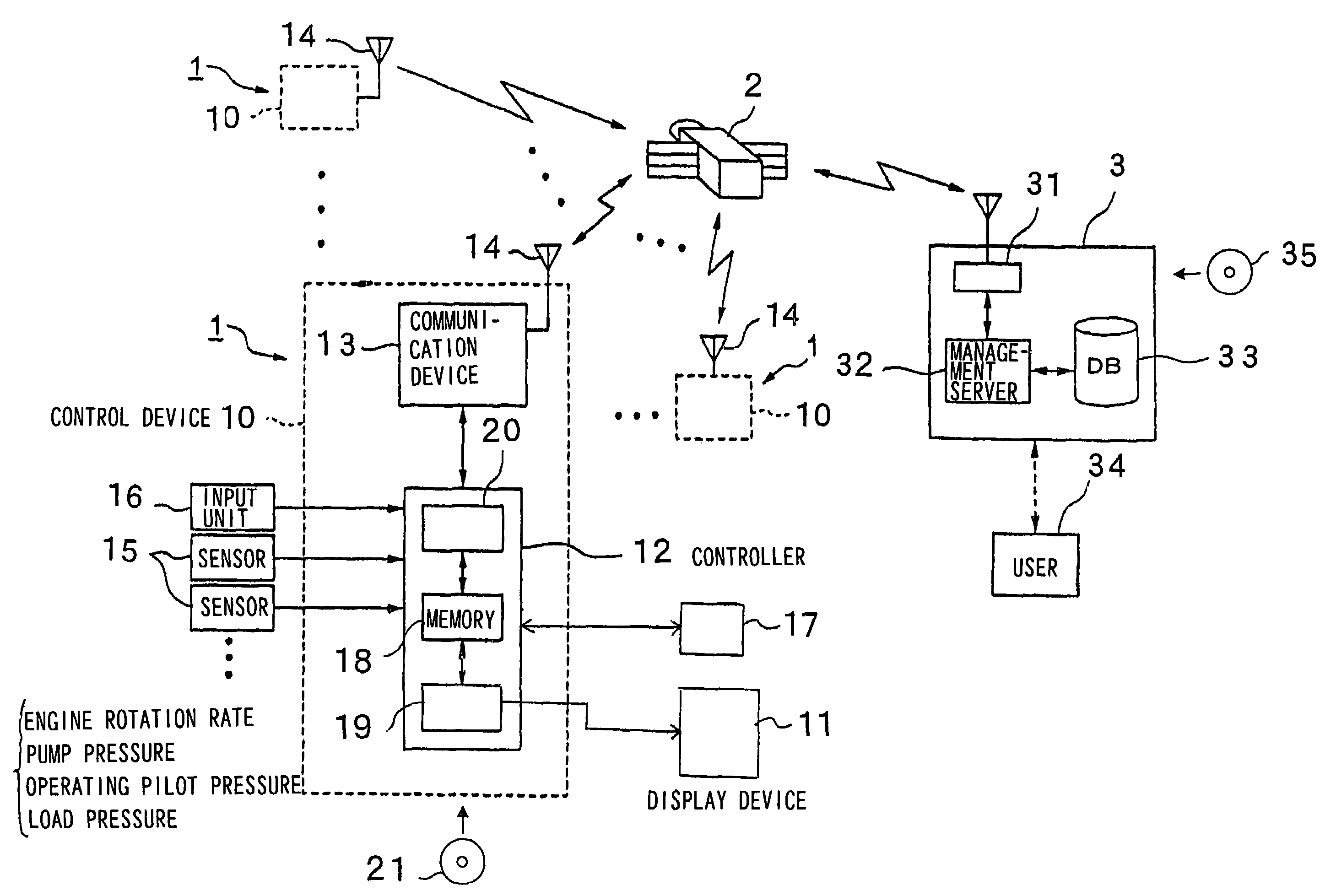
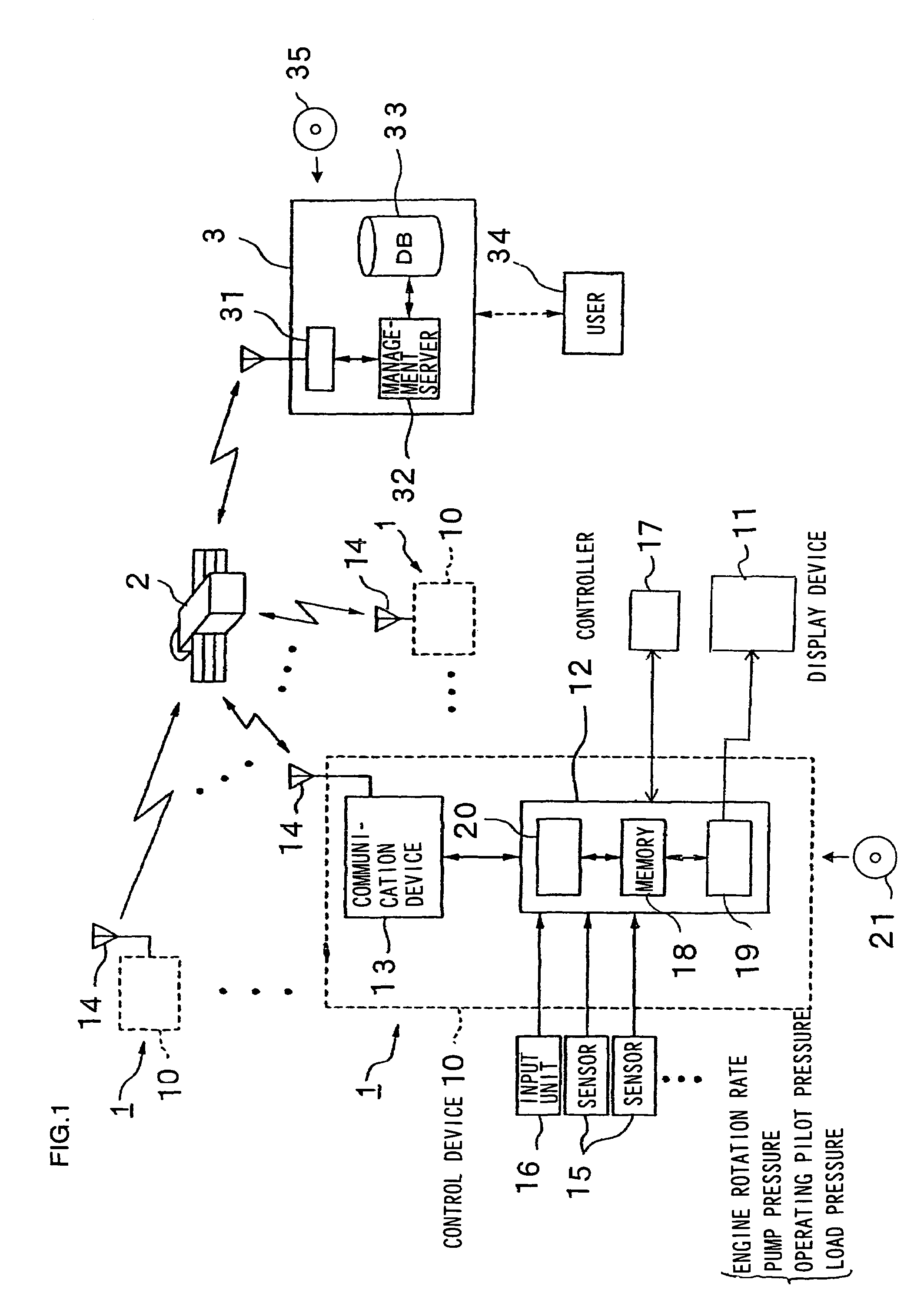
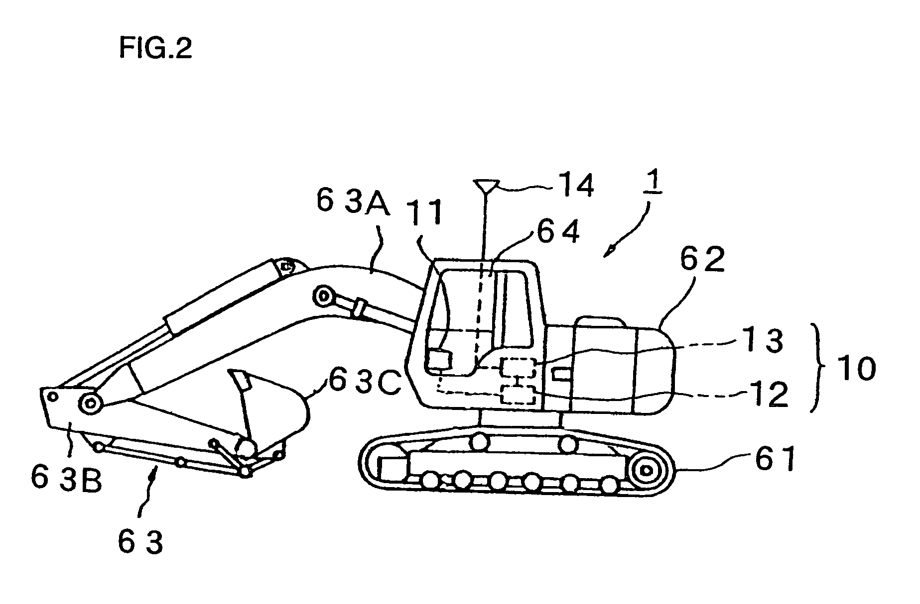
[0048]FIG. 1 is a schematic block diagram of the failure diagnosis system achieved in the first embodiment and FIG. 2 is a side elevation of a hydraulic excavator in which the failure diagnosis system may be adopted. As shown in FIG. 2, a hydraulic excavator 1 includes a traveling lower-structure 61, a swinging upper-structure 62 rotatably mounted on the traveling lower-structure 61 and a work device 63 comprising a boom 63A, an arm 63B and a bucket 63C supported from the swinging upper-structure 62. A control device 10 and a display device 11 such as a monitor are installed in an operator's cab 64. The control device 10 includes a controller 12 and a communication device 13 to which an antenna 14 is connected. A plurality of such hydraulic excavators 1 are deployed on the ground and they exchange information with a center 3 via a communication satell...

second embodiment

[0065]The second embodiment of the present invention is now explained in reference to FIGS. 7 and 8. While the image displayed at the display device 11 is automatically switched in the event of a failure at a sensor 15 and the operation enters the failure diagnosis mode in the first embodiment, the operation enters the failure diagnosis mode in response to a menu selection operation performed by the operator in the second embodiment. The following explanation focuses on the difference from the first embodiment.

[0066]The second embodiment differs from the first embodiment in the specific procedure followed in the signal to transmission / reception between the hydraulic excavator 1 and the center 3. If any problem occurs while driving the hydraulic excavator 1, the operator selects the failure diagnosis mode by operating the input unit 16. In response, an initial screen such as that shown in FIG. 7, for instance, is the brought up at the display device 11 (step S41). In this example, “n...

third embodiment

[0074]FIG. 9 shows the overall structure of the maintenance system for working machines achieved in the third embodiment. Three hydraulic excavators 111A, 111B and 111C are shown in the figure as an example of working machines subscribing to the maintenance service. However, the maintenance work may be performed on working machines other than hydraulic excavators. While numerous hydraulic excavators are managed through this maintenance system for upkeep, management and maintenance in reality, only three hydraulic excavators 111A˜111C, i.e., excavator 1, excavator 2 and excavator 3 are shown in the figure to simplify the explanation. These hydraulic excavators are assigned to individual work sites. The hydraulic excavators 111A˜111C, which are managed through the maintenance system achieved in the embodiment as detailed later include maintenance monitor devices adopting structures identical to one another. The hydraulic excavators 111A˜111C are each mounted with a control device cons...


PUM


Abstract

A working machine failure diagnosis method for performing a failure diagnosis by transmitting and receiving signals through communication devices provided at a working machine and at an information management center, according to the present invention, includes: a first step in which a first signal related to a failure of the working machine is generated at the working machine and the first signal is transmitted to the information management center from the working machine via the communication devices; a second step in which, after the first signal is transmitted, the information management center generates a second signal for identifying a location of the failure based upon the first signal and the second signal is then transmitted from the information management center to the working machine via the communication devices; and a third step in which failure information corresponding to the first signal and the second signal is provided to an operator.

Description

INCORPORATION BY REFERENCE[0001]The disclosures of the following priority applications are herein incorporated by reference:[0002]Japanese Patent Application No. 2001-137809 filed May 8, 2001[0003]Japanese Patent Application No. 2001-219601 filed Jul. 19, 2001TECHNICAL FIELD[0004]The present invention relates to a failure diagnosis and maintenance performed on a working machine and, more specifically, it relates to a failure diagnosis and maintenance performed on a construction working machine such as a hydraulic excavator.BACKGROUND ART[0005]There are systems in the related art in which information (operation data) from construction working machines is transmitted to an information management center where operation data are used to forecast whether or not there is a failure (e.g., Japanese Laid-Open Patent Publication No. 2000-259729). The forecast information generated at the center is provided to the maintenance personnel and a maintenance person performs maintenance work or the ...

Claims


Application Information

Patent Timeline
Patent Type & Authority Patents(United States)
IPC IPC(8): G06F19/00E02F9/20E02F9/24E02F9/26
CPCE02F9/2025E02F9/205E02F9/24E02F9/26G05B19/4185G05B23/0267G05B19/4063G05B2219/45012G05B2219/31454G05B2219/33284E02F9/268Y02P90/80G06F11/00G06Q50/04G06Q50/10
Inventor OGURA, HIROSHIWATANABE, HIROSHISUGIYAMA, GENROKUKARASAWA, HIDEOUMENO, YOSHIYUKITOMIKAWA, OSAMUMIURA, SHUICHIONO, KIYOSHIOCHIAI, YASUSHI
Owner NIHON KENKI CO LTD
Why Eureka
Try Eureka