Network control system, and controller, target and consumer for use in the network control system

a network control and controller technology, applied in the field of network control systems, can solve the problems of degraded transmission efficiency and overhead, and achieve the effect of reliably transmitting and easy and rapid transmission

Inactive Publication Date: 2006-07-18
PANASONIC CORP
View PDF13 Cites 56 Cited by
  • Summary
  • Abstract
  • Description
  • Claims
  • Application Information

AI Technical Summary

Benefits of technology

[0078]In the consumer so constructed, the consumer which has received the data can easily and rapidly decide an internal function control means inside the consumer to which the received data is to be transmitted, whereby the data can be automatically transmitted to an appropriate internal function control means even when

Problems solved by technology

In the above-described construction, however, the controller must repeatedly issue the command according to the buffer amount of the AV device

Method used


Image

  • Network control system, and controller, target and consumer for use in the network control system
  • Network control system, and controller, target and consumer for use in the network control system
  • Network control system, and controller, target and consumer for use in the network control system

Examples


first embodiment

[0109]Initially, with reference to the drawings a description will be given of a network of an AVC system utilizing a network control system according to the present invention.

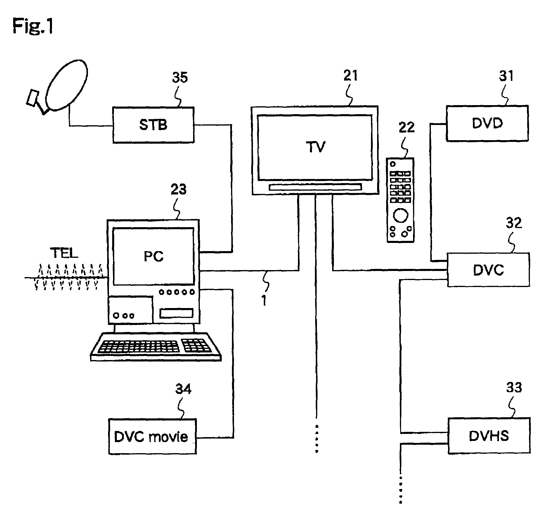
[0110]FIG. 1 is a diagram illustrating an example of a system construction according to a first embodiment of the invention. In this first embodiment, reference numeral 21 denotes a TV, reference numeral 22 denotes a remote controller of the TV 21, reference numeral 23 denotes a personal computer (hereinafter, referred to as “PC”), reference numeral 31 denotes a digital video disk (hereinafter referred to as “DVD”) which is capable of recording and playback, reference numeral 32 denotes a digital video system (hereinafter referred to as “DV system”) digital VTR (hereinafter referred to as “DVC”), reference numeral 33 denotes a VHS system digital VTR (hereinafter referred to as “DVHS”), reference numeral 34 denotes a DV system digital movie (hereinafter referred to as “DVC movie”), and reference numeral 35 deno...

second embodiment

[0313]Next, with reference to the drawings, a description will be given of an AVC system utilizing a network control system having a target whose operation is different from that of the target according to the first embodiment.

[0314]FIG. 15 shows an example of a system construction. In FIG. 15, reference numeral 1541 denotes a TV, reference numeral 1542 denotes a remote controller of the TV 1541, reference numeral 1543 denotes a PC, reference numeral 31 denotes a recordable and playable DVD, reference numeral 32 denotes a DV system DVC, reference numeral 33 denotes a VHS system DVBS, reference numeral 34 denotes a DV system DVC movie, and reference numeral 35 denotes a STB for SC digital broadcasting or the like. These devices are connected with each other by a transmission line 1, thereby constituting an AVC system network.

[0315]These constituents will be described first. The same constituents as those described for the first embodiment are given the same numbers as those shown in ...


PUM


Abstract

A network control system which transmits mass data efficiently, speedily, and reliably, and which includes a controller that can easily decide what a target has transmitted. The controller and the target are used in this network control system. The network control system includes the a controller for transmitting a message, the target for performing processing according to the message, and an initiator for establishing a connection for data transmission between the controller and the target, and the system performs data transmission by using plural protocols. Either or both of the controller and the target is/are present in a device, and the target is constructed so as to receive a message by a first one of the plural protocols and to transmit data onto the connection by a second one of the plural protocols according to the received message.

Description

TECHNICAL FIELD[0001]The present invention relates to a network control system for controlling an audio video computer system (hereinafter referred to as “AVC system”) comprising devices for handling video data, audio data, information data and the like, and to a target, a controller, and a consumer which are used in this network control system. Especially, the present invention relates to a mass data transmission / reception system for transmitting information for generating, on a screen, a graphical user interface (hereinafter referred to as “GUI”) which supports a user operation on the devices, by using graphics, texts and the like.BACKGROUND ART[0002]In recent years, a device control system has been developed to display graphics and icons comprising data and texts for display on a TV screen so as to indicate the functions of the device, and to control the device by selectively controlling the graphics or icons with a remote controller of the TV. Further, a network control system h...

Claims


Application Information

Patent Timeline
IPC IPC(8): H04N7/173H04L12/40H04L12/64H04L29/06H04L29/08H04Q9/00
CPCH04L12/40117H04L29/06H04L69/329H04L67/12H04Q9/00H04L69/18H04L9/40
Inventor YANAGAWA, YOSHIFUMIIITSUKA, HIROYUKI
Owner PANASONIC CORP
Why Eureka
Try Eureka