
Mechatronic transmission control

Inactive Publication Date: 2006-07-25
VITESCO TECH GMBH
View PDF21 Cites 8 Cited by
  • Summary
  • Abstract
  • Description
  • Claims
  • Application Information

AI Technical Summary

Benefits of technology

[0009]On this basis the object of the invention is to design a mechatronic transmission control in such a way that a reliable connection between the sensor system and the electronic control unit of the transmission control can be obtained in a more simple manner.
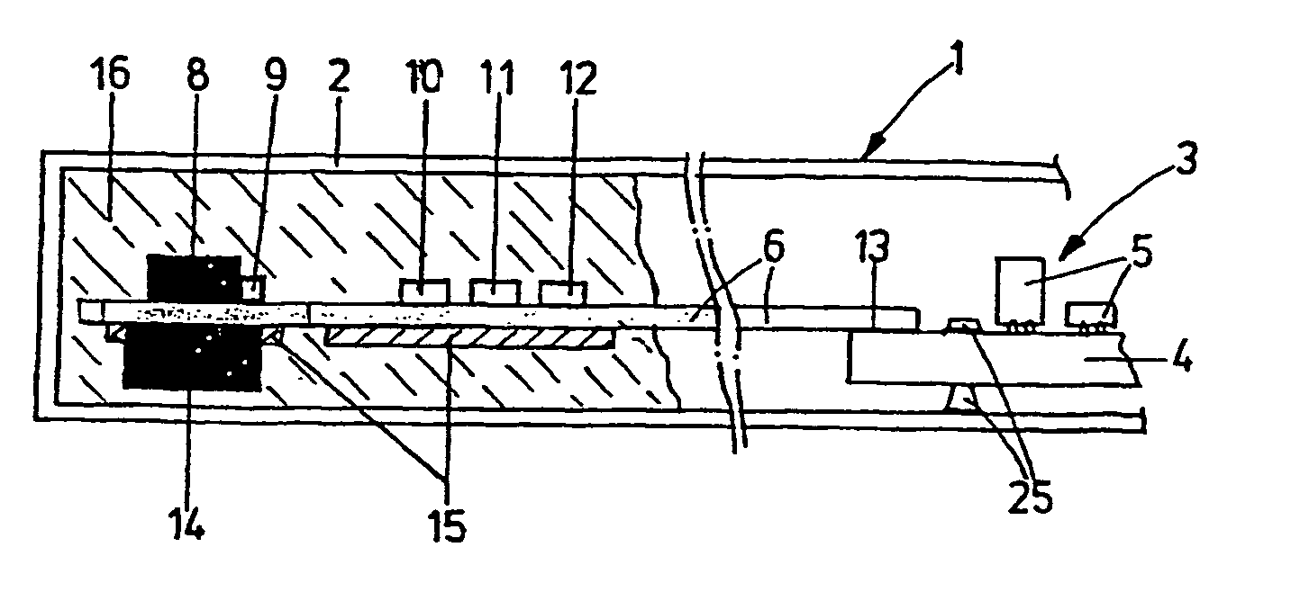
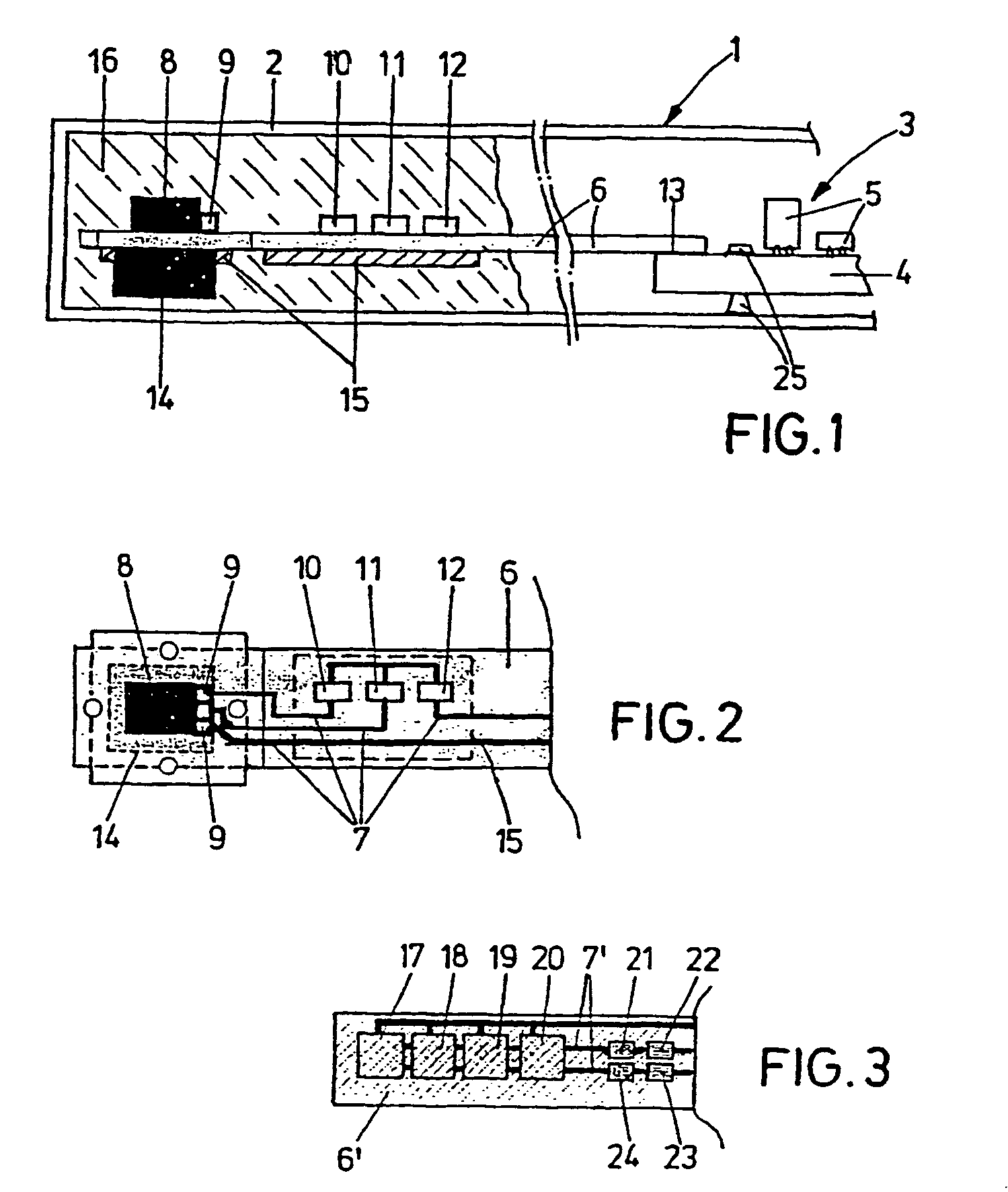
[0011]Through this central idea of the invention it is possible to create a very reliable, simple and flexible connection between the sensor components and the electronic control unit. Because the electronic sensor components can be soldered directly onto the conductor tracks of the flexible printed circuit board, all the plug-in connectors, as are provided and needed for the prior art, can be omitted. As a result, very compact and especially low-profile designs for various sensors can be achieved. There is also considerable freedom in designing the sensor, that can be designed for the installation in a horizontal, vertical or inclined position because the flexible printed circuit board can in principle be bent at will. Therefore there is a completely free choice of mounting location where the sensor element and the possibly existing additional wiring are located. This has the advantage that the location of the transmission can be adapted to any given mechanical boundary conditions such as the fixed position of the sender wheels to be scanned or movable shafts.
[0012]In addition, the invention is also created for a simple-to implement gasket. What this means is that the known sealing compound is easier and more safely managed in combination with a flexible printed circuit board for the electrical and mechanical connection to the sensor components than with the prior art.

Problems solved by technology

The reliability of the electrical connection between the electronic control unit and its sensor components is problematical here.
Mounting location conditions such as those generally found in the transmission must also be taken into account, which often heightens the problem of reliability.
The tight sealing of a connection cable or a nay possible pressed screen is also not without problems from a technical point of view.
Further disadvantages of the connection technology according to the prior art are that the complete arrangement of the sensor with housing, cable and corresponding plug-in connectors requires a lot of space.
To summarize, determined by the requirements outlined above, mechanically costly and also cost-intensive designs for connecting the sensor system to the actual electronic control unit of mechatronic transmission controls are used in the prior art.

Method used


Image

  • Mechatronic transmission control
  • Mechatronic transmission control

Examples


Embodiment Construction

[0017]As is evident from FIG. 1 and FIG. 2, the mechatronic transmission control 1 is accommodated in a housing 2 that is directly flanged onto the transmission of a motor vehicle or integrated into the transmission in a manner not shown in greater detail. The main item of the transmission control 1 is an electronic control unit 3 on the fixed board 4 of which, based on a ceramic substrate for example, the individual electronic components 5 are mounted with conventional technology such as SMD technology. The board 4 is supported in housing 2 by means of suitable mechanical elements 25 as shown schematically in the diagram.

[0018]A flexible printed circuit board 6 is connected to board 4 in the form of an extended strip, in essence a rectangular strip viewed from above. This flexible printed circuit board 6, for example, consists of a flexible but durable electrical insulating foil on which conductor tracks 7 take care of the electrical connection of the electronic components 5 in the...


PUM


Abstract

A mechatronic transmission control is disclosed. The control comprises a housing (2) that can be installed in a motor vehicle transmission, an electronic control unit (3), whose components (5) are arranged on a fixed board (4) in the housing (2), sensor components (8, 10, 11, 12, 14, 17 to 24), which are coupled to the electronic control unit (3) and a flexible printed circuit board (6), on which the sensor components (8, 10, 11, 12, 14, 17 to 24) are positioned and which acts as an electrical and mechanical connection element between the sensor components (8, 10, 11, 12, 14, 17 to 24) and the electronic control unit (3).

Description

CROSS REFERENCE TO RELATED APPLICATION[0001]This application is a continuation of copending International Application No. PCT / DE02 / 00505 filed Feb. 12, 2002 which designates the United States, and claims priority to German application number 10110948.2 filed Mar. 7, 2001.TECHNICAL FIELD OF THE INVENTION[0002]The invention relates to a mechatronic transmission control.BACKGROUND OF THE INVENTION[0003]As background of the invention it must be recorded that, for cost and quality reasons, so-called standalone transmission electronics for automatic transmissions in modern developments are directly integrated into the actual transmission. The unit produced in this way from mechanical components such as a plastic carrier including the actuators, hydraulic components and the necessary electromechanical connection elements upon these, and also sensor components that form the rotational speed, pressure, temperature, route sensors and the like, and from electronic components that usually form ...

Claims


Application Information

Patent Timeline
IPC IPC(8): F16H57/02F16H61/00H05K1/14H05K1/18H05K3/28
CPCF16H61/0006H05K1/147Y10T74/2186H05K3/284H05K1/189H05K5/0082
Inventor JUNGBAUER, BERNDLINCKE, CHRISTOPHLOIBL, JOSEFMENTZEL, GEORG
Owner VITESCO TECH GMBH
Learn More