
Moveable object accountability system

a technology for moving objects and accountability systems, applied in the field of periodic and real-time location history tracking, can solve the problem that no other system meets the objectives

Inactive Publication Date: 2006-07-25
TEETEE COMM
View PDF31 Cites 79 Cited by
  • Summary
  • Abstract
  • Description
  • Claims
  • Application Information

AI Technical Summary

Benefits of technology

[0037]The accountability system for verifying a condition on a moveable object of the present invention will become more readily apparent from a consideration of the following drawings and description.

Problems solved by technology

Although other systems use location logging or tracking devices, no other system meets the objectives of verifying a condition on a moveable object in addition to logging or transmitting date, time and location coordinate data.

Method used


Image

  • Moveable object accountability system
  • Moveable object accountability system
  • Moveable object accountability system

Examples


first embodiment

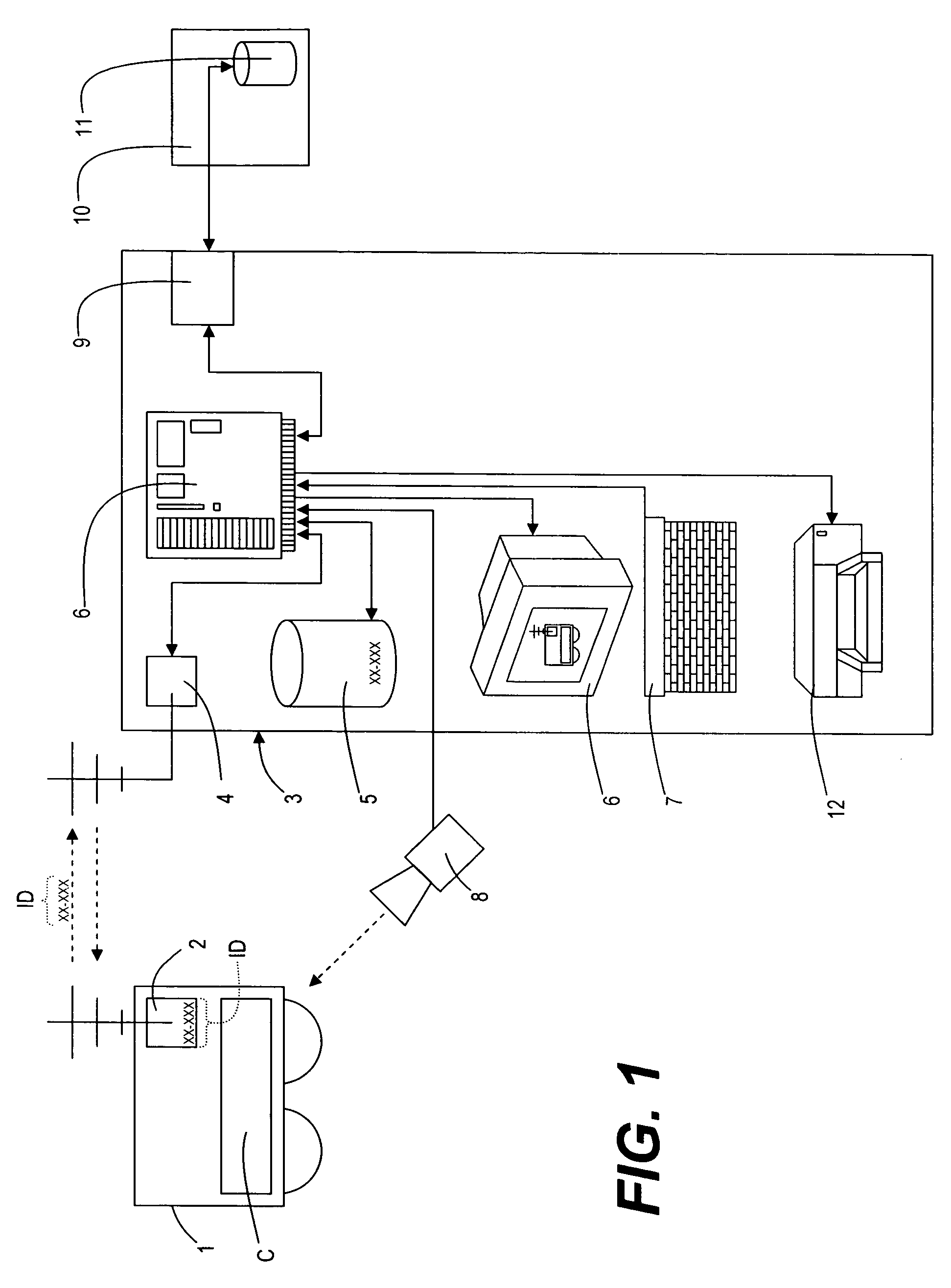
[0044]the invention generally deals with a moveable object having a electronic identification device that communicates a unique identification code to a data collecting verification device which collects additional information about the moveable object and a condition of the moveable object for transmission to a remote database and data processing system.

[0045]FIG. 1 shows a moveable object (1) that anticipates any object capable of being in a different location at different times. One object of the invention is to independently verify a certain condition of or on the moveable object on a periodic basis. This condition, (illustrated in FIG. 1 by reference character “C”), could be one of many items related to the moveable object, such as a visible indication of certain distinguishing characteristics of the moveable object, e.g., the make, model and color of a vehicle, a visible licensing indicator of the moveable object, e.g., a license plate or a registration tag, or a graphical rep...

second embodiment

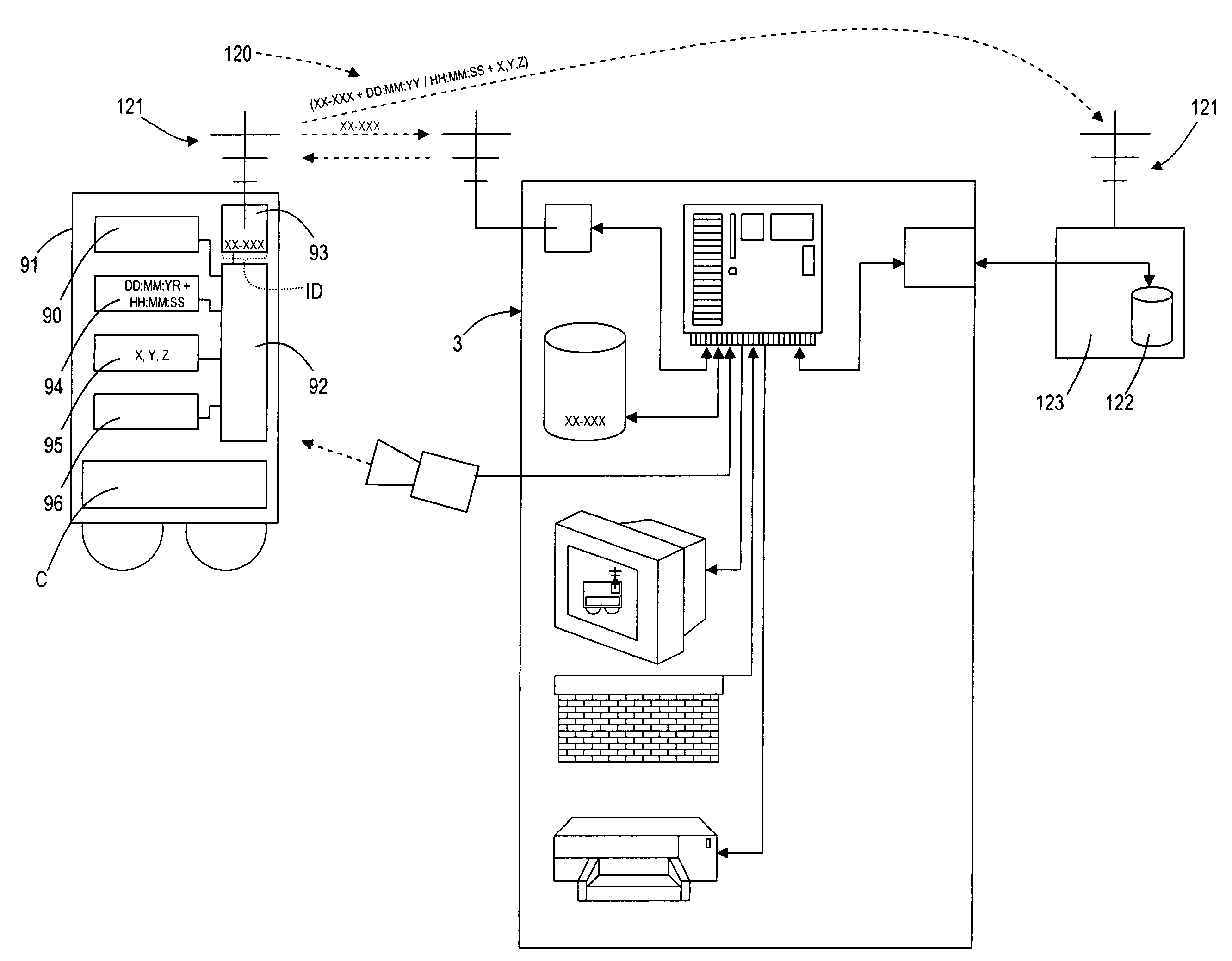
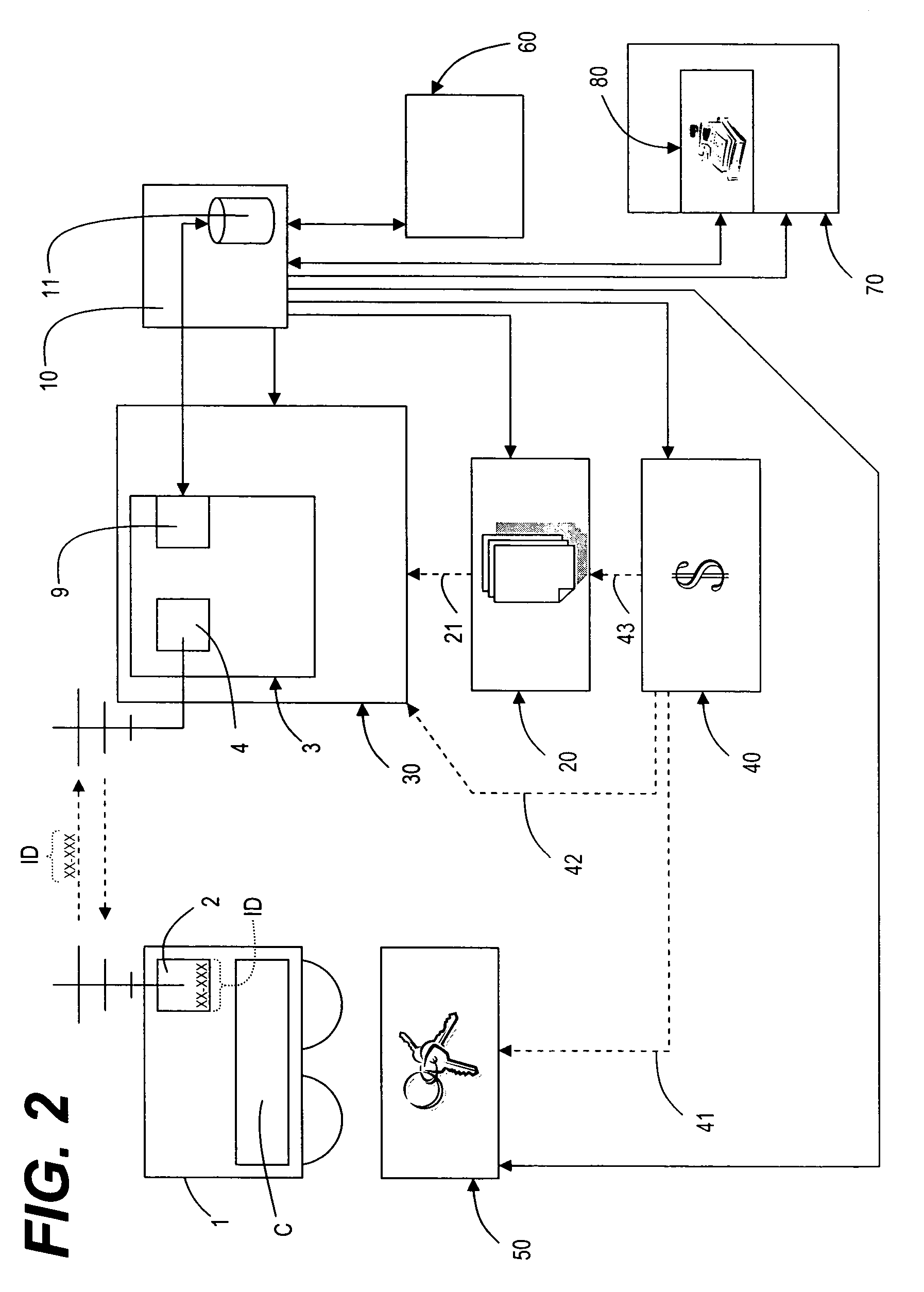
[0058]In the second embodiment, described below, a data logged or real time transmitted location coordinate with date and time data is stored with respect to unique identification codes. The location coordinate with date and time data may then be presented to the client (60) in a geographic map overlay presentation potentially showing every time identified route of every unique identification code the client has contracted for any client specific condition. The communication of the information reports received by the client (60) is based on processing received information at the remote central processor (10) related to the client's contracted unique identification codes (ID), and the received information regarding the assembled and stored data record transmitted by the data verification station (3).

[0059]A retail sales location (70) in communication with the remote central processor (10) receives information from the remote central processor (10) related to the solicitation of owner...


PUM


Abstract

An accountability system for monitoring the status of a certain condition of a moveable object having an electronic identification device with a transmittable unique identification code is disclosed. A verification station with an electronic signal transmission and reception device remotely initiates communication with the electronic identification device on the moveable object and receives the unique identification code. A database at the verification station retrieves information related to the unique identification code, and a camera captures a digital image of the moveable object, while displaying the image and querying a user to input verification data to an input device. A data processing sub-system at the verification station verifies the user's input and compiles a data record of the unique identification code, the digital image, and data input from the user into a data record and stores the compiled record in memory for later communication with a remote storage device.

Description

FIELD OF INVENTION[0001]The general field of the invention relates to periodic and real-time location history tracking with periodic verification of the existence or non-existence of certain predetermined conditions of moveable objects within a time period.[0002]This invention relates to an accountability system for monitoring the status of a certain condition of a moveable object having an electronic identification device with a transmittable unique identification code. A verification station with an electronic signal transmission and reception device remotely initiates communication with the electronic identification device on the moveable object and receives the unique identification code. A database at the verification station retrieves information related to said unique identification code, and a camera captures a digital image of said moveable object while displaying the image and querying a user to input verification data to an input device. A data processing system at the ve...

Claims


Application Information

Patent Timeline
Patent Type & Authority Patents(United States)
IPC IPC(8): G06F19/00G06Q30/00G06Q90/00
CPCG06Q20/203G06Q10/06
Inventor KRESSIN, ROBERTSCHOENEICH, DENISESTOTT, KENNETHLECHER, DONALD
Owner TEETEE COMM
Learn More