
Glass panel

a glass panel and glass technology, applied in the field of glass panels, can solve the problems of undesirable removal of residual stresses during the formation of solder glass seals, significant relaxation of internal stresses in glass sheets, and inability to ignore the influence of heating on glass sheets for all purposes, so as to avoid annealing of either glass sheet

Inactive Publication Date: 2006-07-25
THE UNIV OF SYDNEY
View PDF14 Cites 28 Cited by
  • Summary
  • Abstract
  • Description
  • Claims
  • Application Information

AI Technical Summary

Benefits of technology

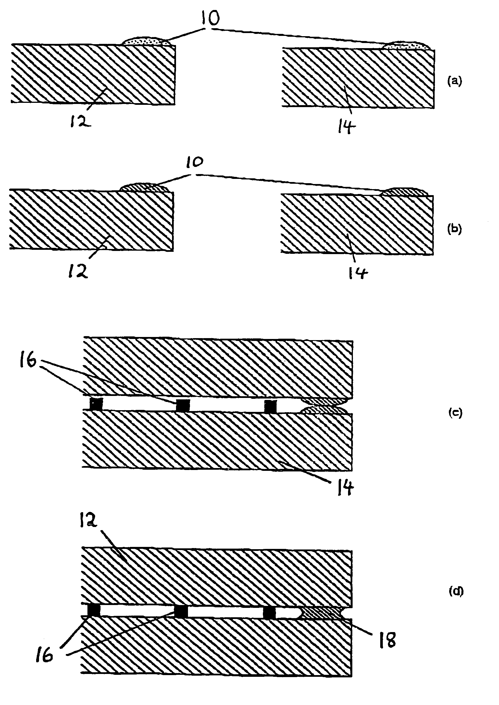
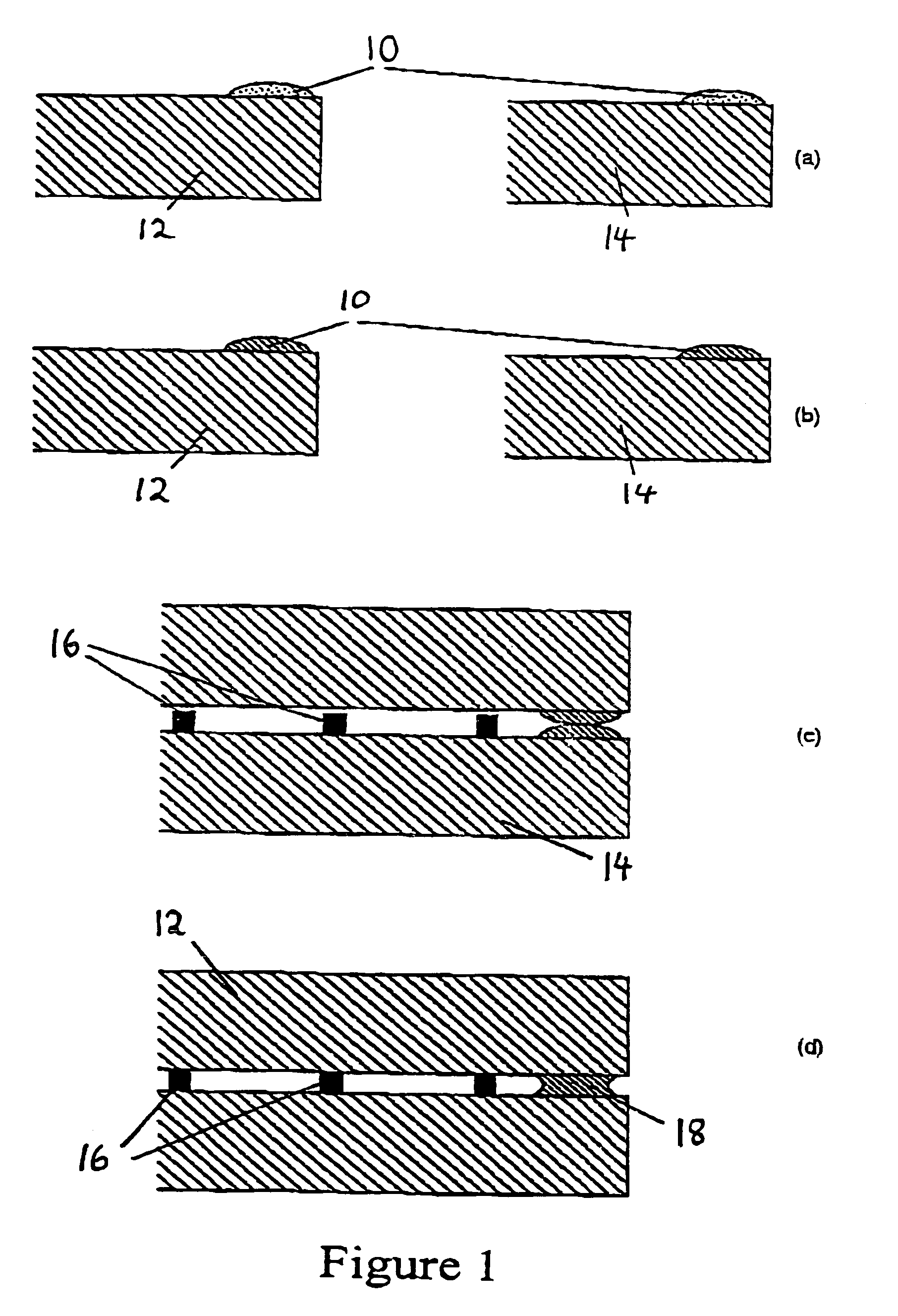
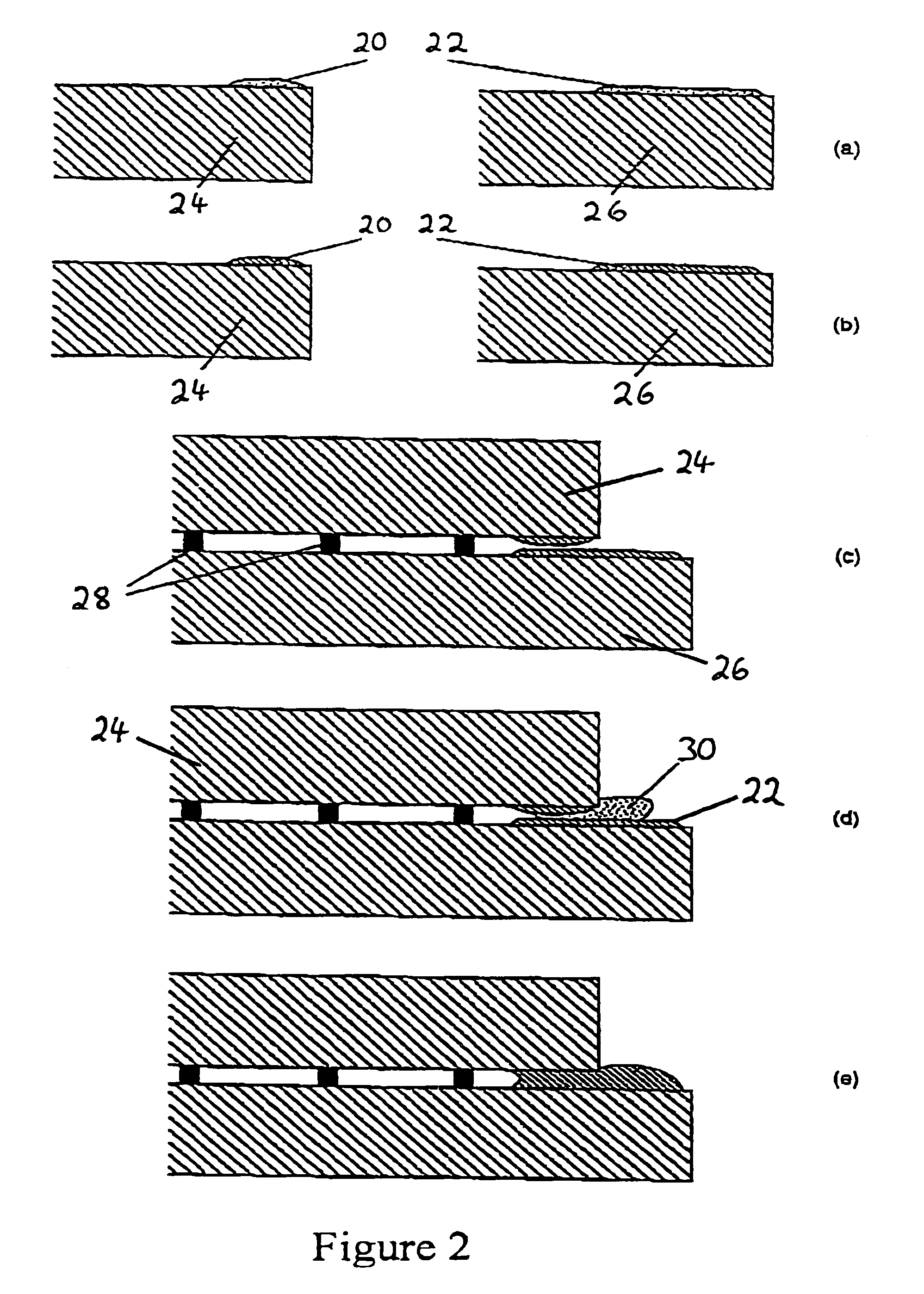
[0009]The present invention may be defined broadly as providing a method of constructing a glass panel which comprises two confronting edge sealed glass sheets. The method comprises the steps of providing a solder glass band around the margin of one surface of each glass sheet; forming, at a first temperature, an hermetic bond between the solder glass band and the associated surface of each glass sheet; positioning the glass sheets in spaced-apart confronting relationship; forming, at a second temperature which is lower than the first temperature, an hermetic seal between the two solder glass bands whilst maintaining the spaced apart relationship between the glass sheets, in a manner that substantially avoids annealing of either glass sheet.

Problems solved by technology

In other words the influence of the heating on the glass sheets cannot be ignored for all purposes.
As an example, the temperatures necessary to form the seal with the process described above can result in a significant relaxation of internal stresses in the glass sheets.
Although the annealing may result in the removal of unwanted stresses in the glass sheets for some applications, for other applications the removal of residual stresses during the formation of the solder glass seal is undesirable.
Since a significant stress relaxation in the glass sheets cannot be avoided during the forming of the hermetic edge seal made from solder glass as described above, it has up until now been impossible to manufacture vacuum glazing which incorporates an hermetic edge seal made from solder glass and which utilize (fully) heat strengthened glass.

Method used


Image

  • Glass panel
  • Glass panel
  • Glass panel

Examples


Embodiment Construction

[0023]We seek to manufacture a glass panel comprising two confronting edge sealed glass sheets. In FIG. 1(a) liquid solder glass 10 is deposited as marginal bands on the surfaces of two glass sheets 12, 14. In FIG. 1(b) the glass sheets 12, 14 are then tempered to establish the necessary stresses within the glass sheets 12, 14 for heat strengthening the same. During the tempering process, the solder glass 10 melts and forms an hermetic bond to the surface of the glass sheets 12, 14. This bond is achieved by interdiffusion of the atoms of the solder glass 10 and the glass sheets 12, 14, typically over a distance of approximately 0.1 μm. As the temperature is decreased at the end of the tempering process, the solder glass solidifies.

[0024]The two tempered glass sheets are then assembled into a configuration illustrated in FIG. 1(c), with the bands of solidified solder glass 10 being positioned on top of each other. In the configuration illustrated in FIG. 1(c), an array of support pil...


PUM

PropertyMeasurementUnit
distanceaaaaaaaaaa
temperaturesaaaaaaaaaa
temperatureaaaaaaaaaa

Abstract

A method of constructing a glass panel which comprises two confronting edge sealed glass sheets, the method comprises the steps of providing a solder glass band around the margin of one surface of each glass sheet, forming, at a first temperature, an hermetic bond between the solder glass band and the associated surface of each glass sheet, positioning the glass sheets in spaced-apart confronting relationship, forming, at a second temperature which is lower than the first temperature, an hermetic seal between the two solder glass bands whilst maintaining the spaced apart relationship between the glass sheets.

Description

[0001]This is a continuation of International patent application PCT / AU00 / 00637, designating the United States, having an international filing date of Jun. 7, 2000, and published in English under PCT Article 21(2) on Dec. 21, 2000, publication No. WO / 0077336, which is hereby incorporated herein by reference in its entirety.FIELD OF THE INVENTION[0002]The present invention relates broadly to glass panels which comprise spaced-apart edge sealed glass sheets. The present invention will be described herein with reference to vacuum glazing, however, it will be appreciated that the present invention does have broader applications including, for example, in automobile windows, glass panel displays or solar collector panels.BACKGROUND OF THE INVENTION[0003]Hermetic seals which are suitable for use in vacuum glazing typically involve the use of solder glass, which is also referred to as glass frit. The term “solder glass” refers to a glass which melts and softens at a lower temperature than ...

Claims


Application Information

Patent Timeline
Patent Type & Authority Patents(United States)
IPC IPC(8): B32B37/06C03C27/06E06B3/663
CPCC03C27/06E06B3/6612E06B3/6617E06B3/66333Y02B80/24Y02A30/249Y02B80/22
Inventor COLLINS, RICHARD EDWARD
Owner THE UNIV OF SYDNEY
Learn More