Laser hardening method

a laser and hardening technology, applied in laser beam welding apparatus, welding apparatus, manufacturing tools, etc., can solve problems such as uneven process accuracy, and achieve the effect of preventing the already hardened parts from being annealed and large width dimensions

Inactive Publication Date: 2007-10-11
YAMAZAKI MAZAK KK
View PDF1 Cites 3 Cited by
  • Summary
  • Abstract
  • Description
  • Claims
  • Application Information

AI Technical Summary

Benefits of technology

[0030]According to the present invention, upon irradiating a laser beam spot on a narrow area on the surface of a work and moving the laser beam t...

Problems solved by technology

If such uneven hardness of the hardened surface occurs, the processing depth of the grinding and cutting performed in the po...

Method used


Image

  • Laser hardening method
  • Laser hardening method
  • Laser hardening method

Examples


Embodiment Construction

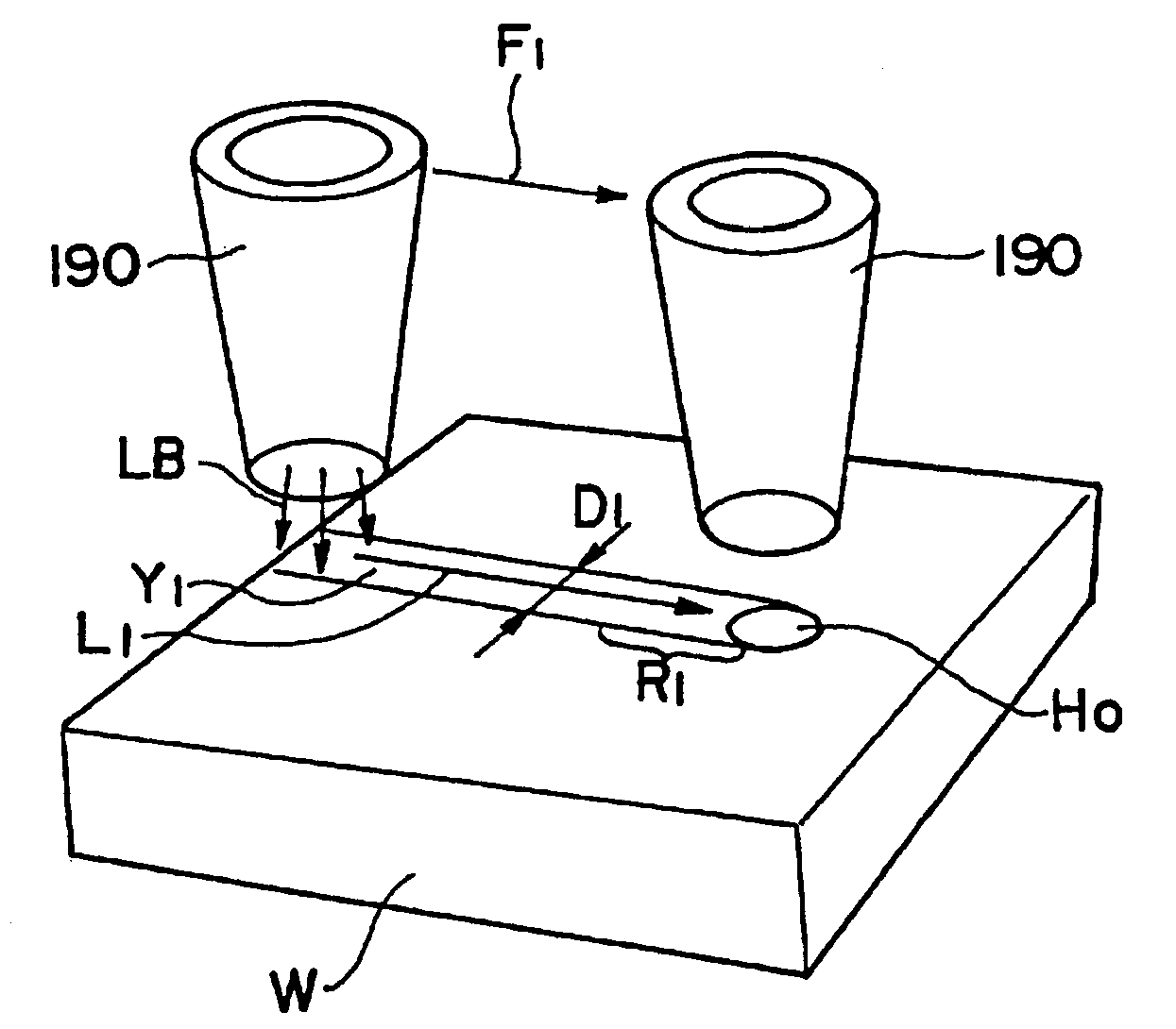
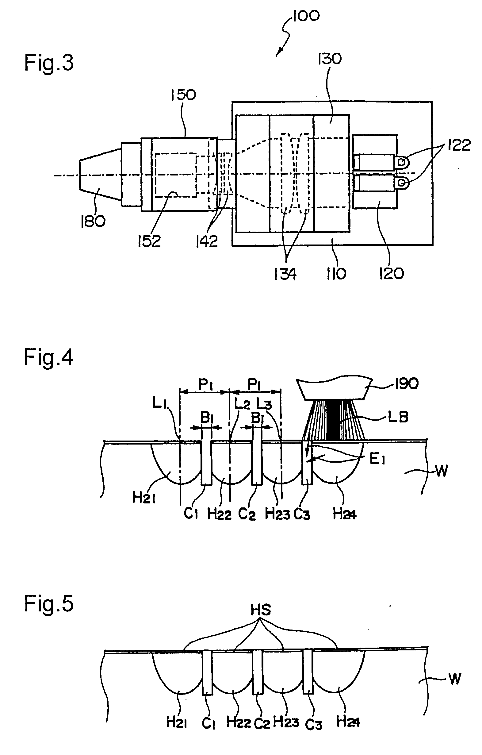
[0042]FIG. 4 is an explanatory view illustrating the outline of the laser hardening method according to the present invention.

[0043]According to the laser hardening method of the present invention, conduits C1, C2 and C3 are provided in advance midway between pitches P1 along which a hardening nozzle 190 performs overlap hardening.

[0044]Here, pitch P1 is set based on the range of thermal energy distribution of laser irradiation on an object determined by the laser output and laser output mode, the shape of the nozzle, the shape of the lens in a laser oscillator unit, and other factors. Further, a width dimension B1 of conduits C1, C2 and C3 is also set based on the range of thermal energy distribution of laser irradiation to an object determined by the laser output and laser output mode, the shape of the nozzle, the shape of the lens within a laser oscillator unit, and other factors.

[0045]FIG. 4 shows the state in which after the nozzle 190 is moved along a center line L3 to process...


PUM

PropertyMeasurementUnit
Energyaaaaaaaaaa

Abstract

The invention provides a laser hardening method capable of preventing adjacent already-hardened layers from being annealed. In the laser hardening method of the present invention, conduits C1, C2 and C3 are processed in advance midway between pitches P1 along which a hardening nozzle 190 performs overlap hardening. After moving the nozzle 190 along a center line L3 to process a hardening layer H23, the nozzle 190 is moved in parallel for a single pitch P1 to perform hardening of a hardening layer H24. Thermal energy E1 of the laser beam LB is also irradiated toward the direction of the hardening layer H23, but it is blocked by the conduit C3 that prevents the laser beam from annealing the hardening layer H23.

Description

[0001]The present application is based on and claims priority of Japanese patent application No. 2006-105455 filed on Apr. 6, 2006, the entire contents of which are hereby incorporated by reference.BACKGROUND OF THE INVENTION[0002]1. Field of the Invention[0003]The present invention relates to a hardening method utilizing semiconductor laser.[0004]2. Description of the Related Art[0005]Japanese Patent Application Laid-Open Publication No. 2003-138314 (patent document 1) discloses an example of a laser hardening device proposed by the present applicant. Japanese Patent Application Laid-Open Publication No. 2005-238253 (patent document 2) discloses a laser hardening tool removably attached to a tool post of a machine tool.[0006]According to the disclosed laser hardening tools, the laser beam from the laser emission source such as the semiconductor laser bar or the semiconductor laser stack is transmitted via an optical fiber or a waveguide to a torch disposed at a leading end of the t...

Claims


Application Information

Patent Timeline
IPC IPC(8): B23K26/08C21D1/09
CPCB23K26/0066B23K26/0051C21D1/09B23K26/0006B23K26/352
Inventor YAMAZAKI, TSUNEHIKOMIYAKAWA, NAOOMI
Owner YAMAZAKI MAZAK KK
Why Eureka
Try Eureka