Polyphasic multi-coil generator

a generator and polyphasic technology, applied in the field of generators, can solve the problems of reducing the efficiency of the generator and the system not creating an efficient generator, and achieve the effect of reducing the rotational resistance of the drive shaft rotation

Active Publication Date: 2006-07-25
DPM TECH INC +1
View PDF5 Cites 108 Cited by
  • Summary
  • Abstract
  • Description
  • Claims
  • Application Information

AI Technical Summary

Benefits of technology

[0017]In an alternative embodiment, the mounting means may be a rigid mounting mounted between the third rotor, each of the first and second rotors and the drive shaft. Instead of the use of clutches, the electrical windings on the rotor arrays in successive stages may be selectively electrically energized, that is, between open and closed circuits for selective windings wherein rotational resistance for rotating the drive shaft is reduced when the circuits are open and increased when the circuits are closed. Staging of the closing of the circuits for successive stator arrays, that is, in successive stages, provides for the selective gradual loading of the generator.

Problems solved by technology

This resistance will continue to grow as the speed of the shaft is increased, thus reducing the efficiency of the generator.
However, the system would not create an efficient generator due to the physical reality that it takes more energy to pull the magnet away from the soft iron core of the coil than would be created in the form of electricity by the passing of the magnet.

Method used


Image

  • Polyphasic multi-coil generator
  • Polyphasic multi-coil generator
  • Polyphasic multi-coil generator

Examples


Embodiment Construction

[0035]I incorporate herein by reference in its entirety my U.S. Provisional Patent Application Ser. No. 60 / 600,723 filed Aug. 12, 2004 entitled Polyphasic Stationary Multi-Coil Generator. Where any inconsistency exists between that document and this specification, for example in the definition of terms, this specification is to govern.

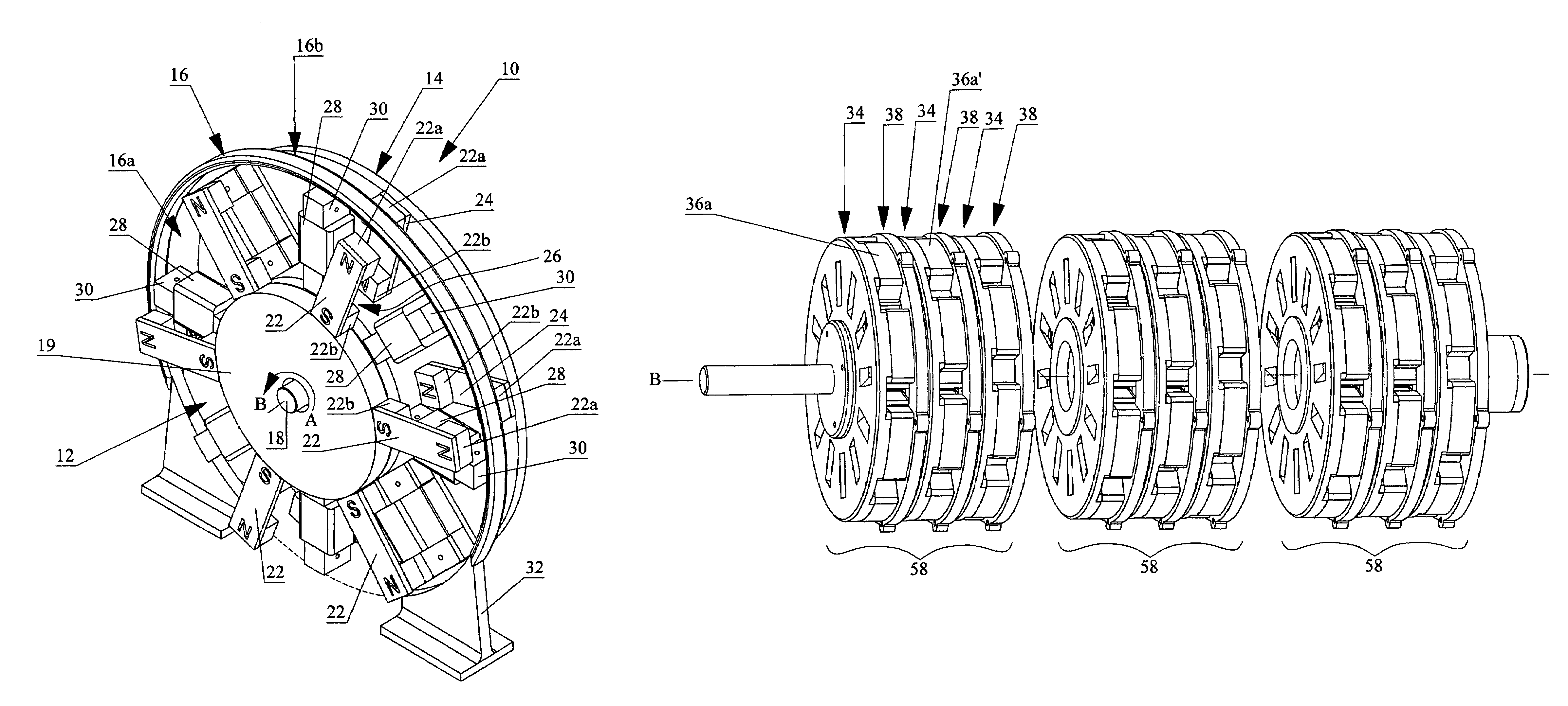
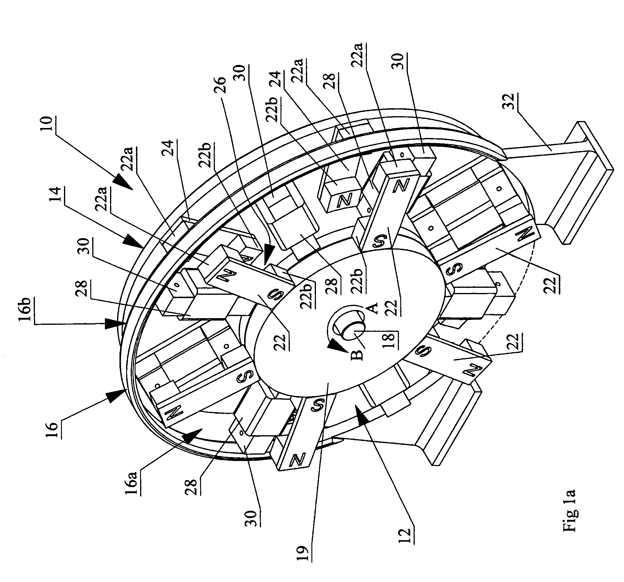
[0036]In FIG. 1a, wherein like reference numerals denote corresponding parts in each view, a single stage 10 of the polyphasic multi-coil generator according to the present invention includes a pair of rotors 12 and 14 lying in parallel planes and sandwiching therebetween so as to be interleaved in a plane parallel and lying between the planes of the rotors, a stator 16. Rotors 12 and 14 are rigidly mounted to a drive shaft 18 so that when drive shaft 18 is rotated by a prime mover (not shown) for example in direction A, rotors 12 and 14 rotate simultaneously at the same rate about axis of rotation B. Feet 32 are provided to mount stator 16 down onto a...


PUM


Abstract

A polyphasie multi-coil generator includes a drive shaft, at least first and second rotors rigidly mounted on the drive shaft so as to simultaneously synchronously rotate with rotation of the drive shaft, and at least one stator sandwiched between the first and second rotors. A stator array on the stator has an array of coils mounted to the stator in a first angular orientation about the drive shaft. The rotors each have an array of magnets which are equally circumferentially spaced around the rotor and located at the same radial spacing with respect to the center of the rotor and the drive shaft. The arrays of magnets on adjacent rotors are off-set by an angular off-set relative to one another.

Description

CROSS REFERENCE TO RELATED APPLICATION[0001]This application is a Continuation-in-Part of U.S. patent application Ser. No. 10 / 976,778 filed Nov. 1, 2004 now abandoned which claims priority from U.S. Provisional Patent Application No. 60 / 600,723 filed Aug. 12, 2004 entitled Polyphasic Stationary Multi-Coil Generator.FIELD OF THE INVENTION[0002]The present invention relates to the field of generators, and more particularly, it relates to a generator having polyphasic multiple coils in staged staggered arrays.BACKGROUND OF THE INVENTION[0003]Conventional electric motors employ magnetic forces to produce either rotational or linear motion. Electric motors operate on the principle that when a conductor, which carries a current, is located in the magnetic field, a magnetic force is exerted upon the conductor resulting in movement. Conventional generators operate through the movement of magnetic fields thereby producing a current in a conductor situated within the magnetic fields. As a res...

Claims


Application Information

Patent Timeline
Patent Type & Authority Patents(United States)
IPC IPC(8): H02K7/20H02K1/22H02K21/00
CPCH02K7/108H02K21/12H02K1/08H02K21/24Y02E10/725H02K1/14Y02E10/72
Inventor RITCHEY, JONATHAN GALE
Owner DPM TECH INC
Why Eureka
Try Eureka