
Communication system using a multiplex signal carrying an auxiliary signal

a communication system and multiplexing technology, applied in the field of communication systems, to achieve the effect of increasing the number of source signals that can be transmitted over the connection

Inactive Publication Date: 2006-07-25
KONINKLIJKE PHILIPS ELECTRONICS NV
View PDF12 Cites 5 Cited by
  • Summary
  • Abstract
  • Description
  • Claims
  • Application Information

AI Technical Summary

Benefits of technology

[0005]The object of the present invention is to provide a communication system according to the preamble in which the number of source signal that can be transmitted over the connection is increased.
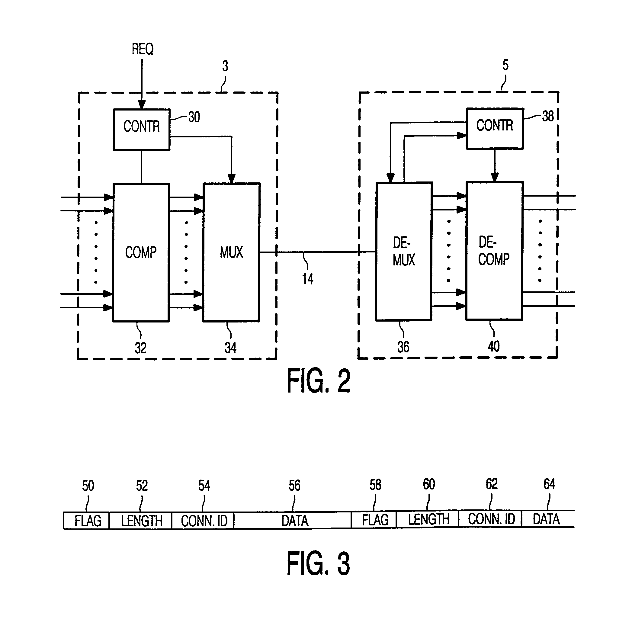
[0007]By making the length of the field carrying the auxiliary signal dependent on the aggregate rate of the source signals to be transmitted, it becomes possible to create more space for transmitting source signals during periods when it is needed. This can easily be done when the auxiliary signal is a signal having no high priority of transmission.
[0011]By transmitting the source signal in packets, it becomes easy to deal with source signals having different bitrates.
[0013]By using a length field in the packet, it is possible to carry to carry source signals with a different bitrate in an efficient way, without the need to keep in the receiver an administration of the length for all packets.

Problems solved by technology

A substantial part of the operational costs of the network of interconnected PBX's is constituted by the costs of the interconnections between the PBX's charged by the operator of the public telephone network.

Method used


Image

  • Communication system using a multiplex signal carrying an auxiliary signal
  • Communication system using a multiplex signal carrying an auxiliary signal
  • Communication system using a multiplex signal carrying an auxiliary signal

Examples


Embodiment Construction

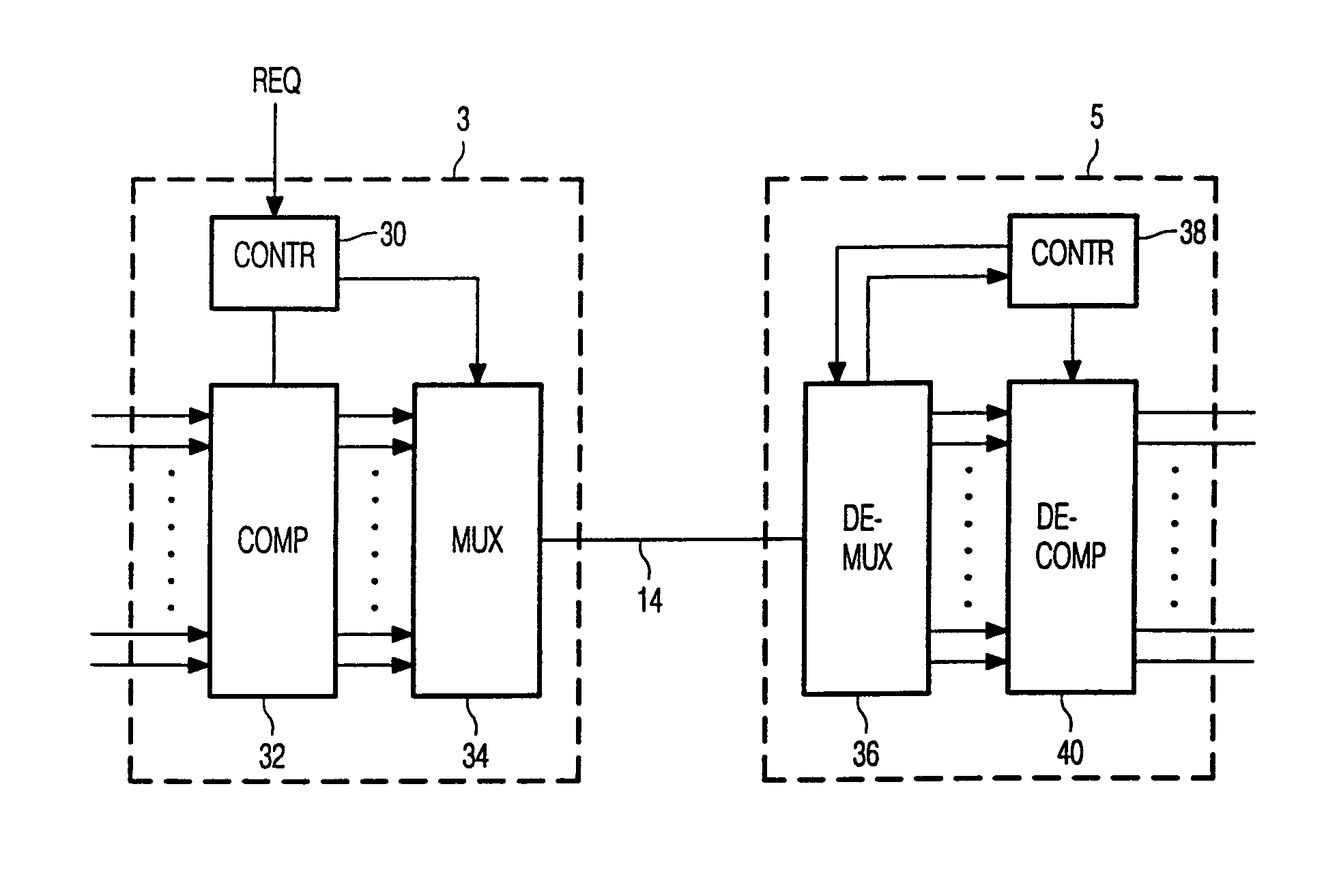
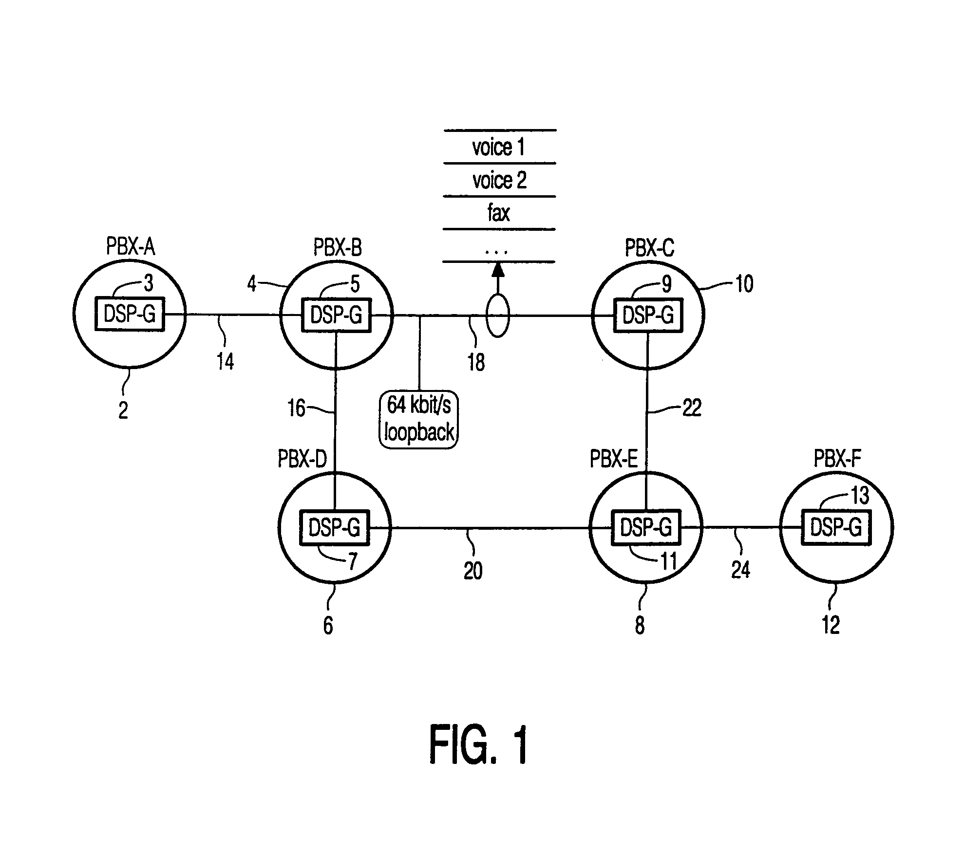
[0023]The communication system according to FIG. 1 comprises a plurality of PBX's 2, 4, 6, 8, 10 and 12. The respective PBX's 2, 4, 6, 8, 10 and 12 comprise a compression server 3, 5, 7, 9, 11 and 13. The PBX's are interconnected via 64 kbit / sec channels 14, 16, 18, 20, 22 and 24. The compression servers can compress speech signals to be transmitted according to several compression algorithms, such as G.728, G.729. They also comprise compression algorithms dedicated for fax signals according to several standards such as V.17, V.29 and V.21 and modem signals according to several standards such as V.34, V.32 and V.22.

[0024]Each of the channels is able to carry a plurality of compressed voice and data signals. The setup according to FIG. 1 is extensively used to reduce the costs of the channels 14, 16, 18, 20, 22 and 24 which are generally routed via a public telephone network. Without using compressions, the required capacity of the channels between the PBX's should have been substant...


PUM


Abstract

In a transmitting node (3) in a transmission system, a plurality of source signals are multiplexed by a multiplexer (34) into a multiplex signal. The multiplex signal is transmitted to a receiving node (5) where it is demultiplexed in the source signals. The multiplex signal comprises a plurality of packets having a flag field, a length field, a connection ID field and a data field. The flag field can be present to enable the receiver to find the beginning of the packet or to carry non-urgent control signals. According to the present invention, the length of the flag field is dependent on the aggregate bitrate of the source signals, making it possible that more source signals can be transmitted over the transmission link under heavy traffic conditions.

Description

BACKGROUND OF THE INVENTIONS[0001]The present invention relates to a communication system comprising a first node having a multiplexer for multiplexing a plurality of source signals into a multiplex signal, the first node comprises transmission means for transmitting the multiplex signal to a second node, the second node comprises a demultiplexer for demultiplexing the multiplex signal into said source signals.[0002]A communication system according to the preamble is known from International Patent Application published under No. WO 98 / 16083.[0003]In the past networked PBX's have been introduced, in which a plurality of PBX's are interconnected via a communication link in order to obtain a larger virtual switch. The PBX's can be at different locations, which can be in different cities and even in different countries. The communication link often comprises a connection over a public telephone network (PSTN).[0004]A substantial part of the operational costs of the network of interconn...

Claims


Application Information

Patent Timeline
Patent Type & Authority Patents(United States)
IPC IPC(8): H04J3/04H04J3/00H04J3/16H04Q3/62H04Q11/04
CPCH04J3/1682H04Q3/62H04Q11/04H04Q2213/13034H04Q2213/13384H04Q2213/13216H04Q2213/1322H04Q2213/13292H04Q2213/13179
Inventor GRUTTER, HENDRIKUS J.
Owner KONINKLIJKE PHILIPS ELECTRONICS NV
Learn More