

Radio communication system using adaptive array antenna
a radio communication system and array antenna technology, applied in power management, polarisation/directional diversity, electromagnetic wave modulation, etc., can solve the problem that the uplink is no longer suitable for the downlink weight, and achieve the effect of improving the downlink as well as the uplink weight, reducing the transmission power of the base station, and increasing the number of simultaneously connected terminal stations
- Summary
- Abstract
- Description
- Claims
- Application Information
AI Technical Summary
Benefits of technology
Problems solved by technology
Method used
Image

Examples
first embodiment
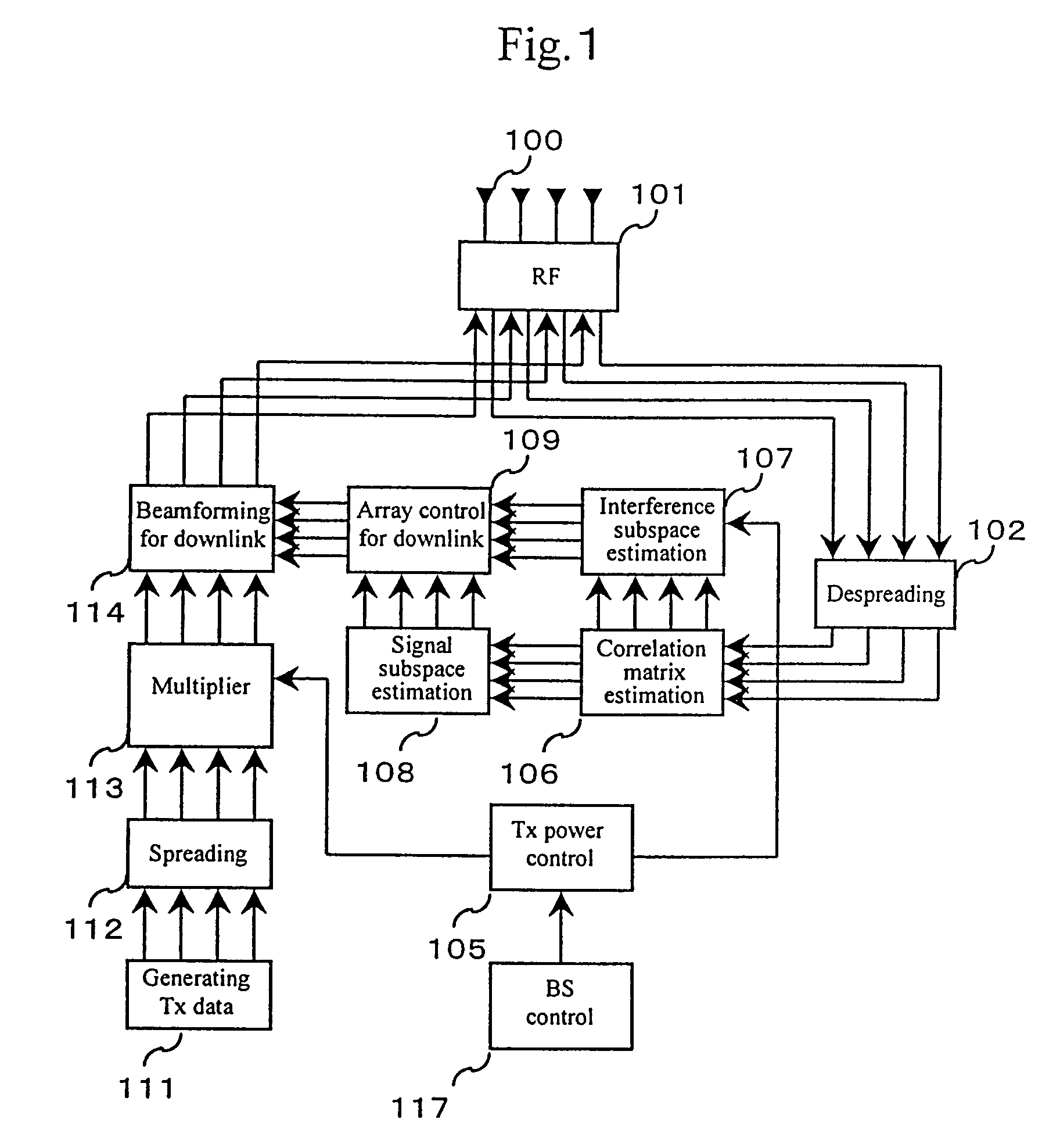
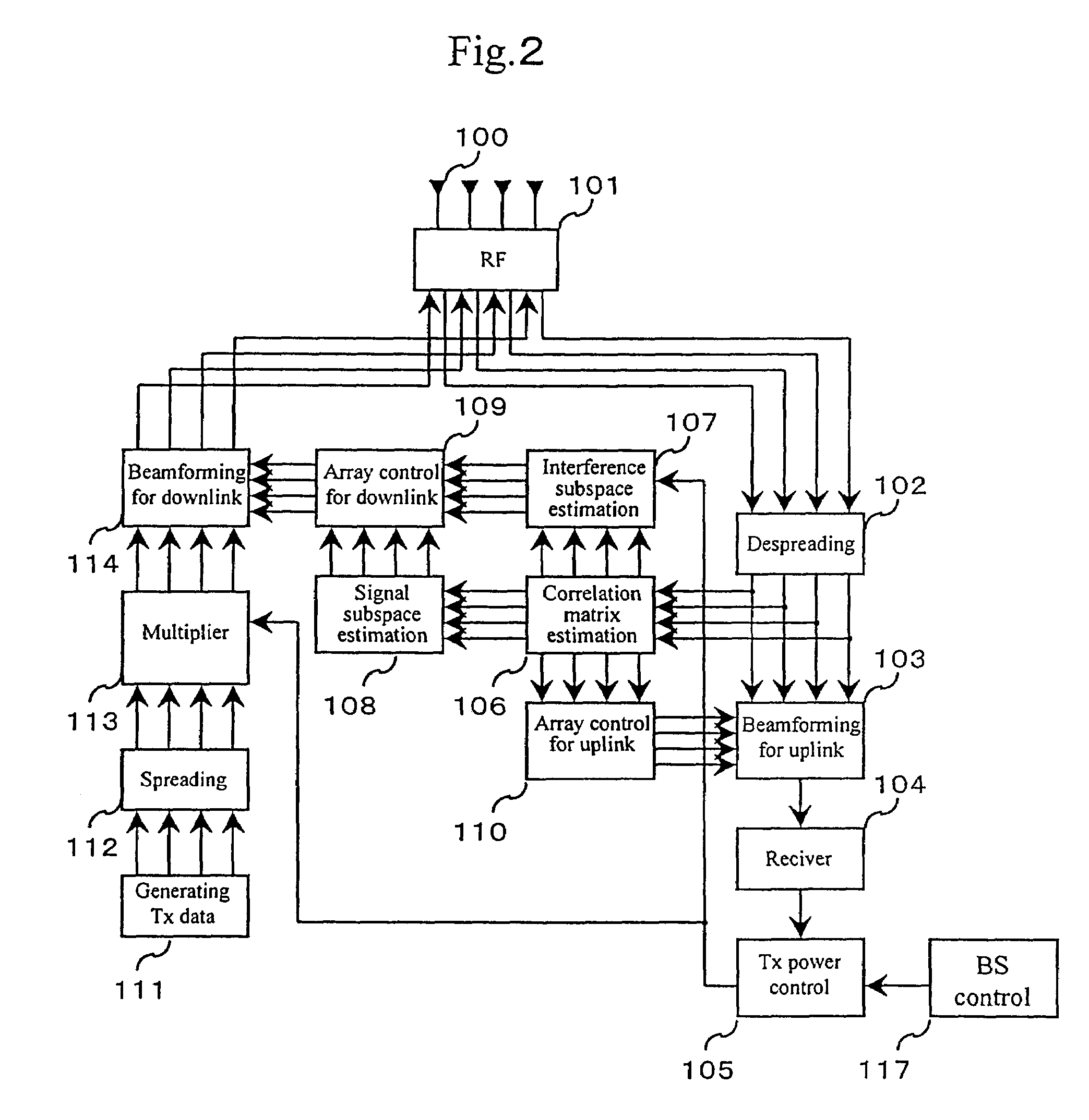
[0017]Referring to FIG. 2 showing the radio communication base station in the first embodiment according to the present invention, a base station is provided with a plurality of antennas 100 constituting an AAA. The antennas 100 distributed in a space to form a sensor capable of sensing incoming waves coming from various arrival angles. The operation of the AAA in an uplink, i.e., an link through which signals are transmitted from mobile stations to the base station, will be described.
[0018]The weight of the array, i.e., array response vector, is determined on the basis of information collected by sensors (antennas) for the operation of the AAA. Generally, the array response vector is referred to as a-vector, which is a weight for purely receiving a desired wave signal in a maximum. There are many possible method of determining the array response vector. A method which accumulates snapshots of a desired wave signal, determines a correlation matrix between the sensors relating to the...
second embodiment
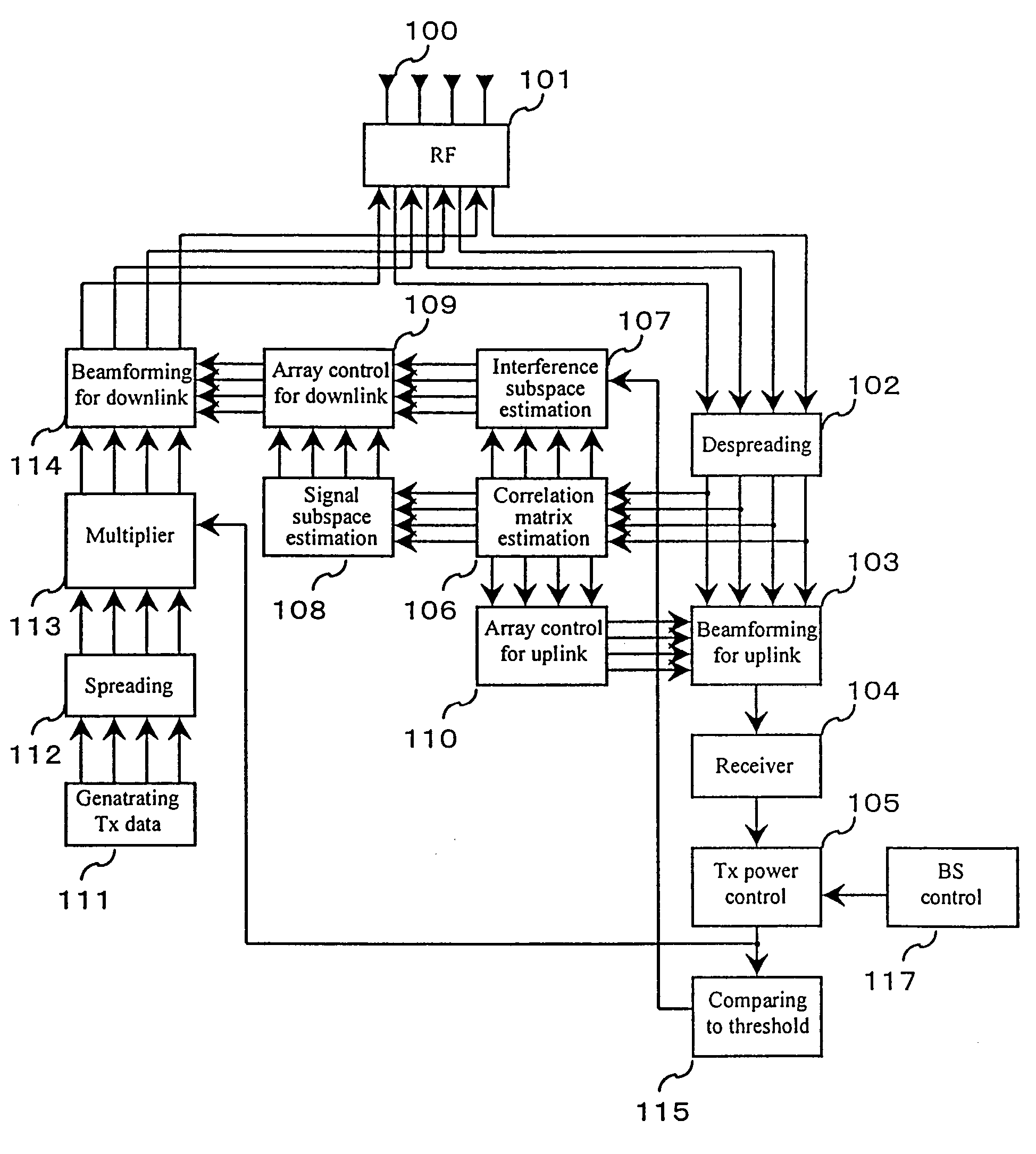
[0049]A radio communication system in a second embodiment according to the present invention will be described with reference to FIG. 3 and Expression (10). Expression (10) shows that interference subspace estimation uses a threshold.
[0050]λi={0(λith)λi(λi≥th)Expression10
[0051]The radio communication system in the second embodiment differs from the radio communication system shown in FIG. 2 in the additional employment of a threshold comparing unit 115. It is an object of the present invention that uses an interference subspace for the estimation of a downlink array weight to increase the S / I in transmission to a maximum by 0. interference because interference is not spatially white. A system that deals with a plurality of terminals, such as a cellular communication base station, does not have large spatial selectivity due to the effect of averaging based on the law of large numbers. If there is a mobile station having a high transmission rate or if a mobile station is located...
third embodiment
[0053]A radio communication system in a third embodiment according to the present invention will be described with reference to FIG. 4 and Expression (11). Expression (11) is an assistance for explaining a low-pass filter.
[0054]λiupdated=(1-δ)λiold+δλinewExpression11
[0055]There have been described methods of deciding the array weight for the downlink by using the subspace information about the incoming waves received through the uplink. In a practical system, transmission power is controlled by a fixed step and transmission power does not vary continuously. Transmission power is a very unstable value controlled in the range of variance due to misestimation of communication quality, communication errors in transmission control and information transfer, and delayed control due to delayed communication. If an interference subspace is built by directly using this value, the operation of the subspace is unstable. Therefore, a method that uses a low-pass filter for control instead of...
PUM
 Abstract
Description
Claims
Application Information