Multipolar pacing method and apparatus

a multi-polar, pacing technology, applied in the direction of internal electrodes, transvascular endocardial electrodes, therapy, etc., can solve the problems of unnatural ventricular contraction pattern, ineffective pacing from the atrial appendage, and stimulation from this site that is counter to the heart's natural operation

Active Publication Date: 2006-07-25
MEDTRONIC INC
View PDF30 Cites 49 Cited by
  • Summary
  • Abstract
  • Description
  • Claims
  • Application Information

AI Technical Summary

Problems solved by technology

However, pacing from the atrial appendage is ineffective if the conduction between the atria and ventricles is blocked.
Stimulation from this site is counter to the heart's natural operation.
Therefore, ventricular pacing sends an electrical impulse that moves from the bottom to the top of the ventricles, and from the right to the left ventricle, causing an unnatural ventricular contraction pattern.
Some studies have put forth the proposition that significant problems are associated with pacing from the ventricular apex.
It has been speculated that physiological pacing can cause ventricular wall abnormalities, inferior localized myocardial perfusion defects and mitral regurgitation.
In addition, pacing from the ventricular apex has been alleged to create myofibrilar disarray and fatty deposits throughout the ventricles.

Method used


Image

  • Multipolar pacing method and apparatus
  • Multipolar pacing method and apparatus
  • Multipolar pacing method and apparatus

Examples


Embodiment Construction

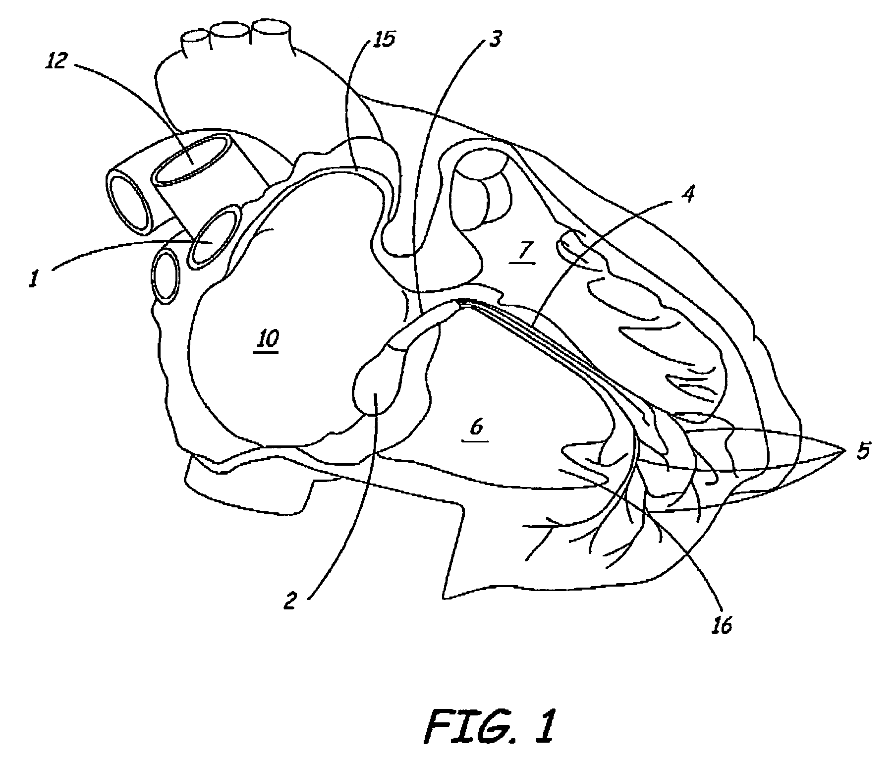
[0027]FIG. 1 is a schematic diagram of a right side of a heart having an anterior-lateral wall peeled back to present a portion of a heart's intrinsic conduction system and chambers of a right atrium 10 and a right ventricle 6. Pertinent elements of the heart's intrinsic conduction system, illustrated in FIG. 1, include a sinoatrial (SA) node 1, an atrioventricular node 2, a bundle of His 3, a right bundle branch 4, and Purkinje fibers 5. SA node 1 is shown at a junction between a superior vena cava 12 and right atrium (RA) 10. An electrical impulse starting at SA node 1 travels rapidly through RA 10 and a left atrium (not shown) to AV node 2. At AV node 2, the impulse slows to create a delay before passing on through a bundle of His 3, which branches, in an interventricular septum 7, into a right bundle branch 4 and a left bundle branch (not shown) and then, apically, into Purkinje fibers 5. Following the delay, the impulse travels rapidly throughout right ventricle (RV) 6 and a le...


PUM


Abstract

A physiological pacing system including a physiological pacing lead having an electrode array and a means for fixation, including a collar for securing the fixation means to a lead body of the pacing lead, is inserted into a bore within a heart wall at a physiological pacing site. The system further includes a means to create the bore, the means being a piercing tip, which is either coupled to a piercing tool or the pacing lead. The piercing tool may be an elongated hollow shaft into which the pacing lead is slideably insertable or a stylet wire, which is slideably insertable within a lumen of the pacing lead. Once the electrode array is implanted within the bore, a first pair of electrodes is selected for sensing and a second pair of electrodes is selected for pacing.

Description

FIELD OF THE INVENTION[0001]The present invention generally relates to implantable medical devices, and more particularly to a medical electrical lead providing improved physiological pacing capabilities.BACKGROUND OF THE INVENTION[0002]Various types of pacing leads have been developed for endocardial introduction into different chambers of a patient's heart, typically a right ventricle, right atrial appendage, or coronary sinus. These flexible leads are usually constructed having an outer polymeric sheath encasing one or more electrical conductors. The conductors may be arranged coaxially or co-linearly and are insulated from one another. A distal end of each conductor is coupled to one or more electrodes while a proximal end of each conductor is coupled to a contact of a connector that is in turn coupled to an implantable pulse generator (IPG). The distal end of the lead is implanted to be positioned within the heart so that the electrodes may deliver pacing therapy by both sensin...

Claims


Application Information

Patent Timeline
Patent Type & Authority Patents(United States)
IPC IPC(8): A61N1/05
CPCA61N1/0573A61N1/056
Inventor KLEIN, GEORGE J.LASKE, TIMOTHY G.
Owner MEDTRONIC INC
Why Eureka
Try Eureka