Energy consumption in electrical drive

a technology of electrical drive and energy consumption, which is applied in the direction of electric devices, instruments, transportation and packaging, etc., can solve the problems of difficult to achieve simple control arrangements, and significant drawbacks of simple control arrangements, so as to achieve cost-effective and simple new corresponding arrangements

Inactive Publication Date: 2006-07-25
ABB OY
View PDF10 Cites 13 Cited by
  • Summary
  • Abstract
  • Description
  • Claims
  • Application Information

AI Technical Summary

Benefits of technology

[0046]Another advantage of the invention is that by means of it, the benefits of an electrical drive that is particularly based on a frequency converter and of applied speed regulation are found out in a simple and effective way in comparison with other control systems. A particular advantage of the invention is that thereby different electrical drives can be compared, and the best po...

Problems solved by technology

However, simple control arrangements have remarkable drawbacks.
An optimal process capacity, which ensures the best quality of the process, is extremely difficult to achieve with simple control arrangements.
Apart from this, with each direct on-line start-up, there is a risk of electrical and/or mechanical damage.
An extremely remarkable drawback with simple control arrangements is that they consume a lot of energy, and energy is particularly consumed in various losses.
This means that energy losses are created in the control device.
Also the maintenance of the device is often difficult.
Changing production volumes by mechanical means is usually very inefficient.
It has been estimated that in the maintenance of throttling control, there is consumed even ten times as much money as in the maintenance of a frequency converter drive.
The problem is how to measure and/or evaluate energy consumption and particular...

Method used


Image

  • Energy consumption in electrical drive
  • Energy consumption in electrical drive
  • Energy consumption in electrical drive

Examples


Embodiment Construction

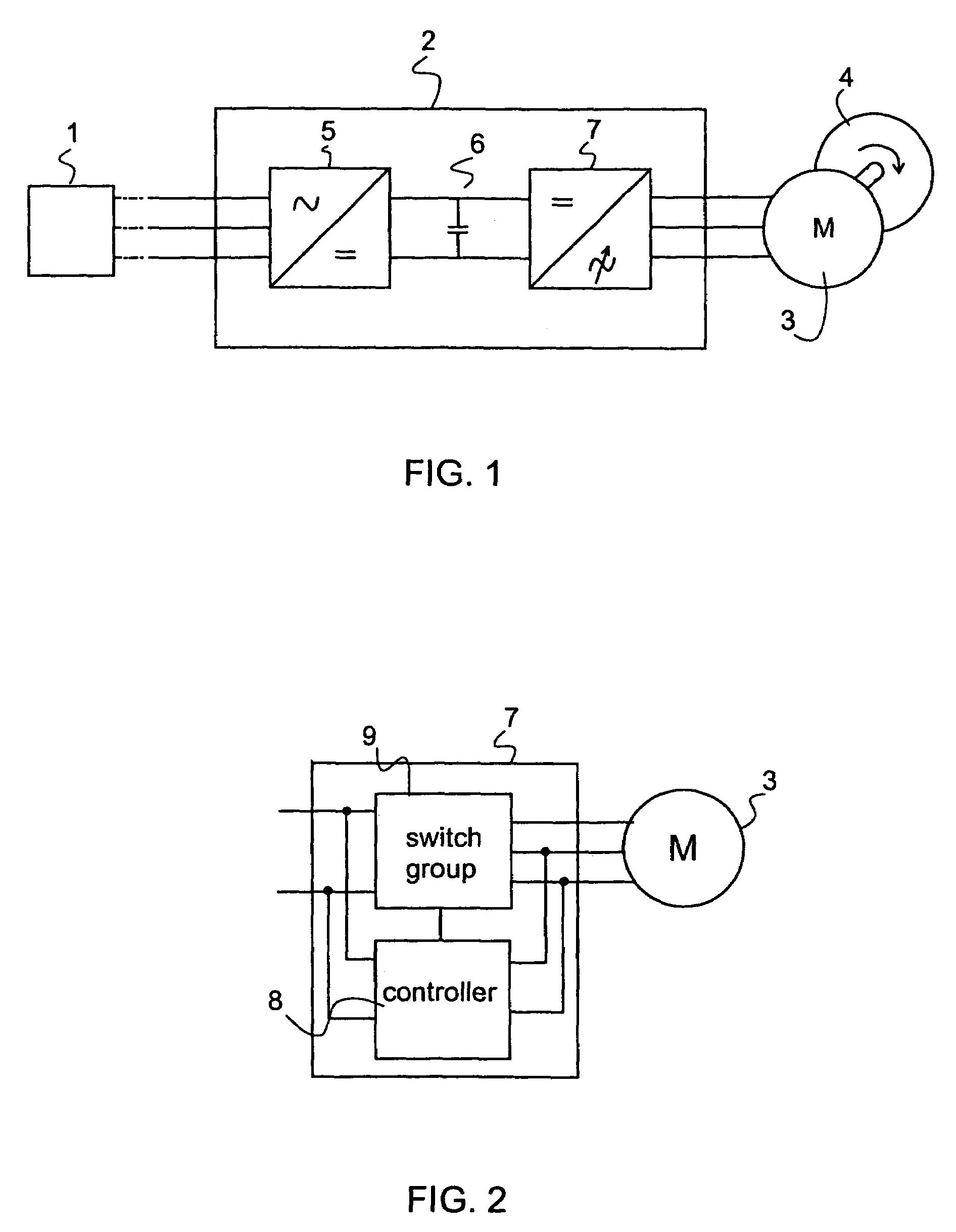
[0054]An electrical drive, one example of which is illustrated in FIG. 1, comprises an electricity supply 1, a control unit that is advantageously realized as a frequency converter 2, an AC motor 3, in this case a three-phase motor. The electrical drive is operated for running, for example rotating, a load 4 that can be for instance a pump. The electricity supply 1 comprises an alternating current mains, such as a three-phase mains, or a corresponding alternating current source for feeding electric energy into the electrical drive. The AC motor 3 is advantageously a squirrel cage motor, which is the most common electric motor used in industrial processes.

[0055]In this embodiment the control unit, in this case a frequency converter 2, comprises a rectifier 5, a direct voltage intermediate circuit 6 and an inverter 7. The inverter 7 of the frequency converter 2 is illustrated as a block diagram in FIG. 2. The inverter 7 comprises a switch group 9 and a controller 8. By means of the co...


PUM


Abstract

The invention relates to a measurement and evaluation method of energy consumption in an electrical drive having a control unit and an AC motor and an arrangement for realizing the method. The method has the following steps. Data of the state of the AC motor, such as power and frequency, is read at measurement points and saved. The energy consumption of the electrical drive is calculated in predetermined measurement intervals. The energy consumption of the virtual AC motor fed by constant-frequency input current is calculated and the energy consumption of an alternative control arrangement is defined in said measurement interval and they are added together. The energy consumption of the electrical drive is compared with the added total energy consumption of the virtual AC motor and the alternative control arrangement in order to evaluate the energy savings achieved by the electrical drive in the measurement time period in question.

Description

BACKGROUND OF THE INVENTION[0001](1) Field of the Invention[0002]The invention relates to a method for measuring and evaluating energy consumption in electrical drive, said electrical drive including a control unit and an alternating current (AC) motor, in which method data of the state of the AC motor, such as power and frequency, is read and saved.[0003]The invention also relates to an arrangement for realizing the method. In the arrangement for measuring and evaluating electrical drive energy consumption, said electrical drive includes a frequency converter and an AC motor, and said control unit includes a measurement unit for measuring the state data of the AC motor, such a power and frequency.[0004](2) Description of Related Art[0005]At present, machines, devices and processes in general, particularly in the industrial sector, are used by electrical drives, where an essential element is an electric motor. Electrical drive is composed of a suitable electricity supply circuit, an...

Claims


Application Information

Patent Timeline
IPC IPC(8): G01R21/00G01R22/00H02P27/06
CPCH02P27/06G01R22/00
Inventor RANTA, KARI
Owner ABB OY
Why Eureka
Try Eureka