
Multi-thread execution method and parallel processor system

a parallel processor and execution method technology, applied in the direction of multi-programming arrangements, memory allocation/allocation/relocation, instruments, etc., can solve the problems of inability to obtain desired performance, inability to achieve desired performance, and insufficient execution of actual programs in many cases, so as to increase the degree of parallelization of threads and the effect of effective use of processor resources

Inactive Publication Date: 2006-07-25
NEC CORP
View PDF13 Cites 48 Cited by
  • Summary
  • Abstract
  • Description
  • Claims
  • Application Information

AI Technical Summary

Benefits of technology

The present invention provides a method and system for executing multiple threads in parallel using a plurality of thread execution units. The method involves merging threads that are being terminated and yet to be settled into a new thread to increase the degree of parallelization. The system includes a communication path for connecting the thread execution units, a temporary buffer for each unit, and means for managing the units as being at three states: a free state where fork is possible, a busy state where a thread is being executed, and a term state where a thread being terminated and yet to be settled exists. The system also includes a cache memory for holding version information and making a selective response based on the version information and the sequential execution order of the threads. The technical effects of the invention include effective use of processor resources, increased parallelization of threads, and improved performance and efficiency of parallel processor systems.

Problems solved by technology

Although a multi-thread execution method is premised on that preceding threads whose execution is settled are executed in parallel, actual programs in many cases fail to obtain sufficient threads whose execution is settled.
In addition, there is a possibility that desired performance could not be obtained because a rate of parallelization is suppressed to be low due to such limitations as dynamically determined dependence, compiler analysis capability and the like.
However, there is a problem that as well as instruction-basis non-program order execution, with respect to a normal dependence relationship regarding a memory in particular, instructions should be basically executed according to a program order and when the program order execution is deterministically made, the effect of improving execution performance of non-program order execution can not be fully obtained.
In particular, thread-basis non-program order execution has a serious problem because non-program order execution is prevented on a basis of a thread composed of a plurality of instructions.
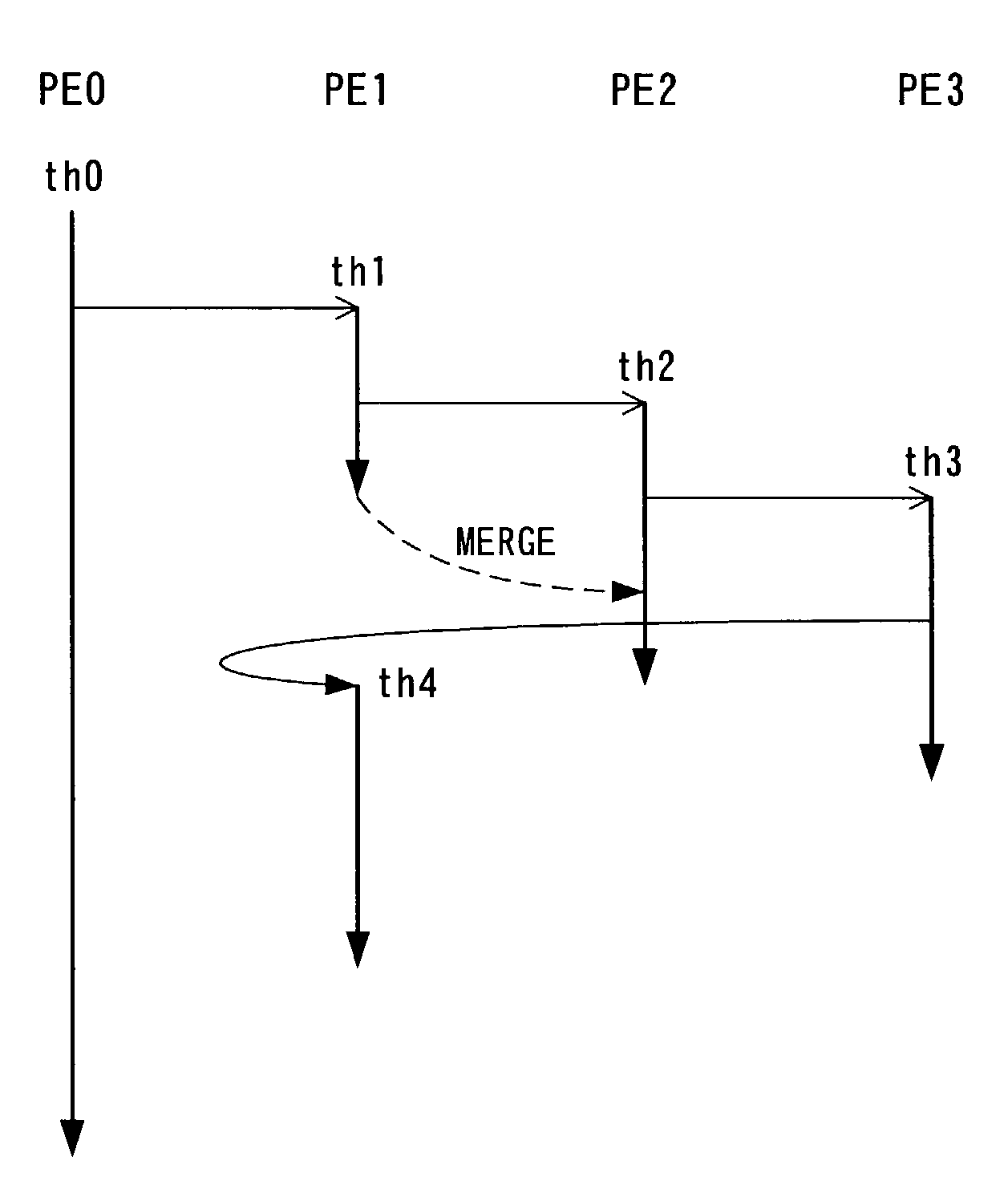
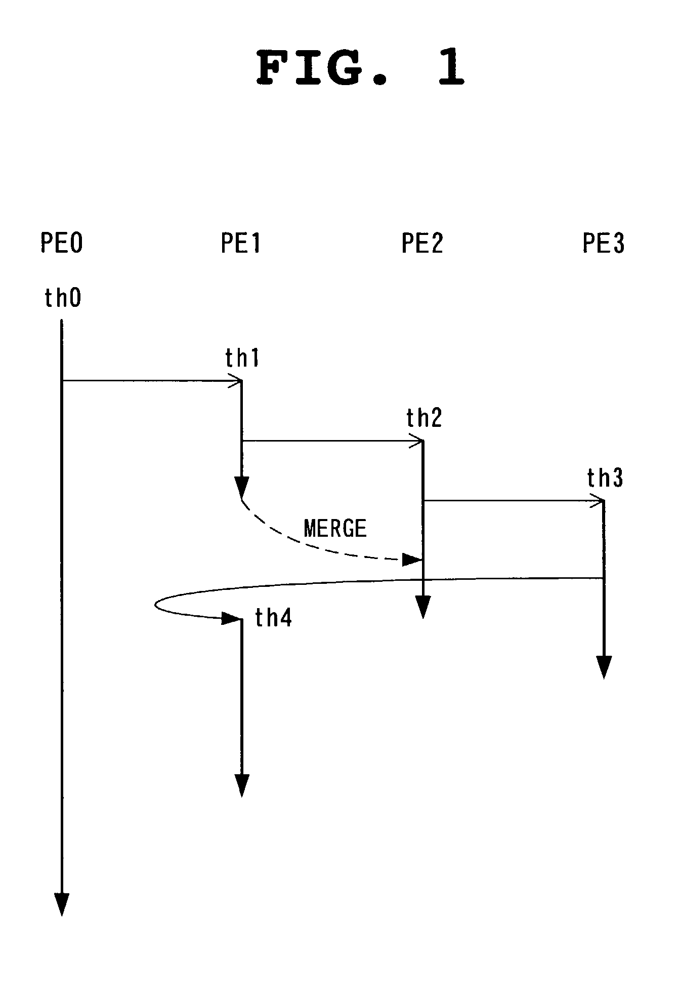
While a parallel processor system in which adjacent processors are connected in a ring in a single direction has an advantage of simplifying hardware, it has a disadvantage of failing to use processor resources effectively when a particle size of a thread varies to result in degrading a degree of parallelization of threads. FIGS. 16 and 17 show such a case.
In addition, in a case where the thread th1 is a speculative thread, how to handle processing results of the thread th1 poses a problem when releasing resources of the processor PE1.

Method used


Image

  • Multi-thread execution method and parallel processor system
  • Multi-thread execution method and parallel processor system
  • Multi-thread execution method and parallel processor system

Examples


embodiment

[0106]Outlines of an embodiment conforming to the foregoing policy will be as follows.

[0107]First, in addition to a valid flag, a change flag, an address tag and a data entry, etc., a cache line has at least a version identifier vid indicative of a version of data. The version identifier vid has as many bits as the number of processors that the multi-processor system has excluding its own processor, with each bit corresponding to other processor excluding its own processor.

[0108]When write for a store instruction or the like is executed, a version identifier vid of a target line is set. Bits to be set are those corresponding to processors executing all the master threads of threads in question excluding a merged thread and the remaining bits are reset.

[0109]When a certain thread is terminated, in version identifiers vid of all the cache lines of the cache memories of all the processors excluding a processor executing the thread in question, reset a bit corresponding to the processor...

specific example

[0114]Next, with reference to FIG. 7, a specific example of the present embodiment will be described with respect to a multi-processor system composed of four processors P0 to P3 noting to the processor P1.

[0115]In (1) of FIG. 7, in a thread th0 executed on the processor P1, a store instruction (stA) for an address A is executed to make the version of the cache line of the address A be 100. In the figure, “A, 100” indicates that the address is A and the value of the version identifier vid is 100. The respective bits of the version identifier vid correspond to the processors P0, P2 and P3, respectively, from the left. In other words, since at this time point, for the thread th0, its master thread is executed only at the processor P0, the version identifier vid is set to be 100.

[0116]In (2) of FIG. 7, after the thread th0 is terminated at the processor P1, a thread th1 is generated from a thread c01 by free fork. The thread th0 is merged into a thread C00. Since the merging will cause...

application example

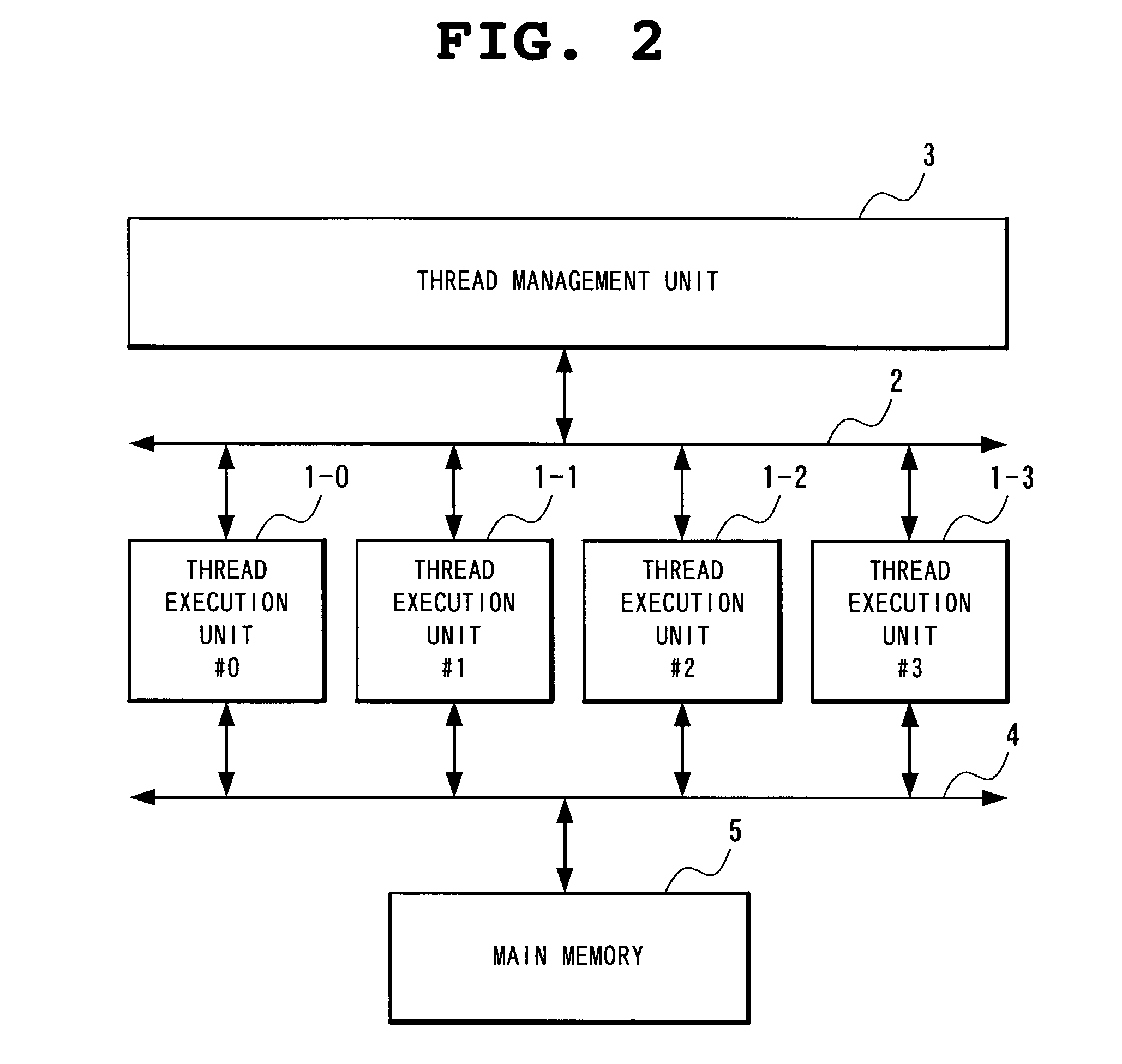
[0130]Next, detailed description will be made of an example of application of the above-described cache memory control method to the parallel processor system shown in FIG. 2 with reference to the drawings.

[0131]FIG. 8 is a block diagram showing a structure of the thread execution unit 1-i. With reference to FIG. 8, the thread execution unit 1-i includes a processor 10, a cache memory 11 and a cache control unit 12, with the processor 10 connected to the bus 2 and the cache control unit 12 connected to the bus 4. The bus 4 includes a request bus 13, a response bus 14 and a data bus 15 as buses related to cache control.

[0132]The processor 10 is connected to the cache memory 11 and the cache control unit 12 to execute a thread in parallel with a processor of other thread execution unit. The processor 10 is connected to the thread management unit 3 and a processor of other thread execution unit through the bus 2 to communicate control information related to thread execution such as thr...


PUM


Abstract

In a parallel processor system for executing a plurality of threads in parallel to each other by a plurality of thread execution units, the respective thread execution units allow for forking of a slave thread from an individual thread execution unit into another arbitrary thread execution unit. The respective thread execution units are managed in three states, a free state where fork is possible, a busy state where a thread is being executed, and a term state where a thread being terminated and yet to be settled exists. At the time of forking of a new thread, when there exists no thread execution unit at the free state, a thread that the thread execution unit at the term state has is merged into its immediately succeeding slave thread to bring the thread execution unit in question to the free state and conduct forking of a new thread.

Description

BACKGROUND OF THE INVENTION[0001]1. Field of the Invention[0002]The present invention relates to a parallel processor system for executing a plurality of threads which are obtained by dividing a single program in parallel to each other by a plurality of processors, and more particularly, to a parallel processor system enabling forking to a processor having a thread being terminated and yet to be settled.[0003]2. Description of the Related Art[0004]Among methods of processing a single program in parallel by a parallel processor system is a multi-thread execution method of executing instruction streams called threads obtained by dividing a program in parallel to each other by a plurality of processors. Literatures reciting this method are, for example, Japanese Patent Laying-Open No. 10-27108 (hereinafter referred to as Literature 1), “Proposal of On Chip Multiprocessor Oriented Control Parallel Architecture MUSCAT” (Proceedings of the Parallel Processing Symposium JSPP97, Japanese So...

Claims


Application Information

Patent Timeline
Patent Type & Authority Patents(United States)
IPC IPC(8): G06F9/45G06F9/38G06F12/08G06F9/46G06F9/48G06F9/50G06F9/52G06F15/167G06F15/177
CPCG06F9/3842G06F9/4806G06F9/3851
Inventor OHSAWA, TAKUSHIBAYAMA, ATSUFUMIMATSUSHITA, SATOSHI
Owner NEC CORP
Learn More