Hydraulic drive vehicle

Active Publication Date: 2006-08-01
KANZAKI KOKYUKOKI MFG
View PDF9 Cites 44 Cited by
  • Summary
  • Abstract
  • Description
  • Claims
  • Application Information

AI Technical Summary

Benefits of technology

[0008]A first object of the present invention is to provide a hydraulic driving vehicle comprising front and rear transaxles incorporating respective hydraulic motors and a pump unit separated from the front and rear transaxles which are fluidly connected by piping so as to form a hydraulic cir

Problems solved by technology

However, the effect of cooling hydraulic fluid is insufficient because the cooling effect by the cooling fan is transmitted to the hydraulic fluid through the casing of the pump unit.
The pr

Method used


Image

  • Hydraulic drive vehicle
  • Hydraulic drive vehicle
  • Hydraulic drive vehicle

Examples


Embodiment Construction

[0042]Embodiments of a hydraulic driving working vehicle according to the present invention will be described.

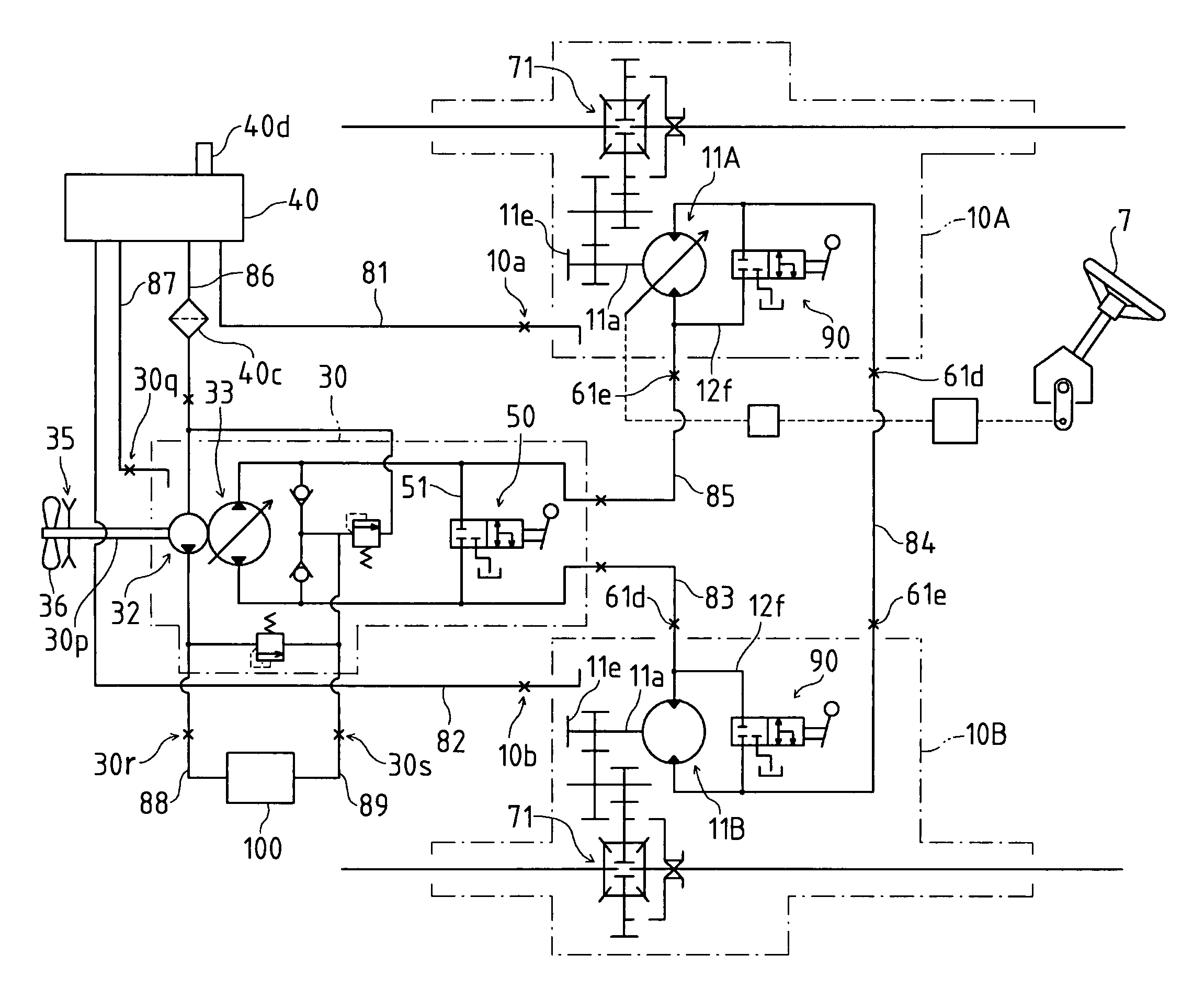
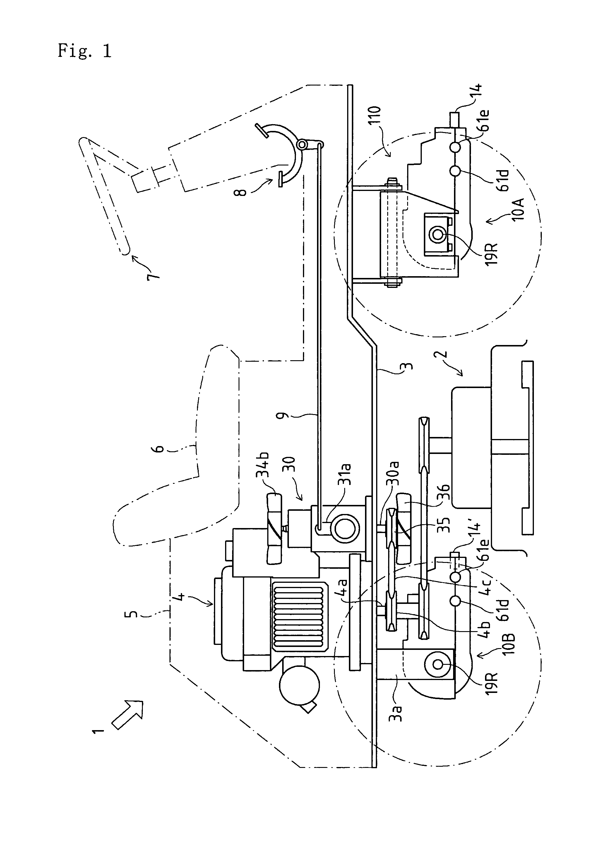
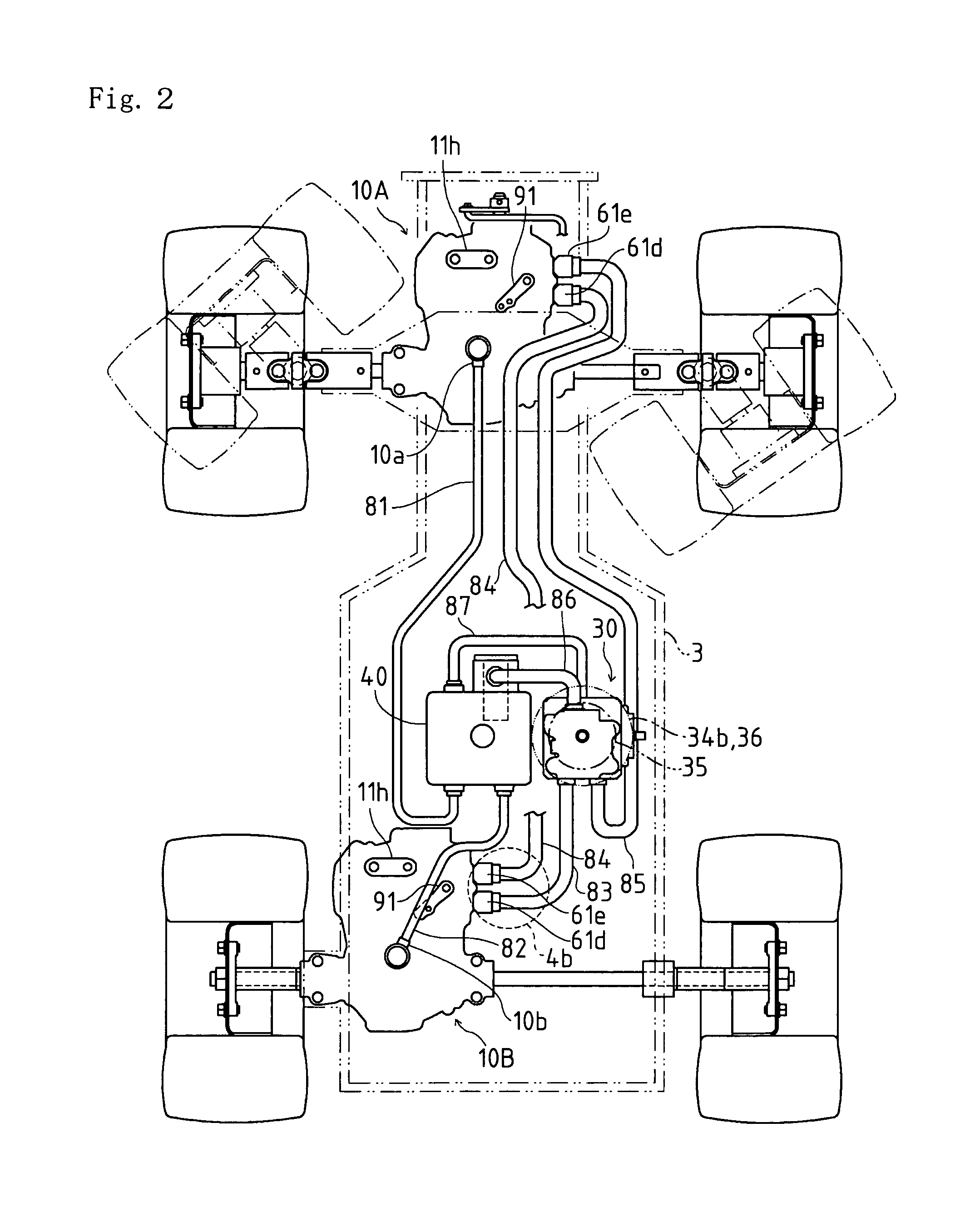
[0043]Referring to a working vehicle 1 shown in FIGS. 1 and 2, a front transaxle 10A, a rear transaxle 10B, and a mower 2 between transaxles 10A and 10B are disposed below a chassis 3. Rear transaxle 10B is laterally eccentrically disposed in vehicle 1 so that left and right axles 19L and 19R projecting laterally outward from rear transaxle 10B are different in length from each other. Left and right brackets 3a holding respective bearings are hung down from chassis 3 so as to journal respective axles 19L and 19R through the respective bearings adjacent to rear tires on outer ends of axles 19L and 19R. Front transaxle 10A is suspended from chassis 3 as discussed later. An engine 4, and a pump unit 30 incorporating a hydraulic pump 33 driven by engine 4 are mounted on chassis 3. Engine 4 and pump unit 30 are enclosed in a bonnet 5 on which a driver's seat 6 is mounted.

[0044]A ...


PUM


Abstract

A hydraulic driving vehicle comprises front and rear transaxles incorporating respective hydraulic motors, and a pump unit separated from the front and rear transaxles. The pump unit incorporates a hydraulic pump having a pump shaft. A hydraulic circuit is formed by piping between the pump unit and the front and rear transaxles so as to circulate hydraulic fluid between the hydraulic pump and the hydraulic motors. A reservoir tank of the hydraulic fluid is connected to the hydraulic circuit by piping. A first cooling fan blowing air away from the pump unit and a second cooling fan blowing air toward the pump unit are disposed oppositely to each other with respect to the pump unit and drivingly connected to the pump shaft. At least a pipe for the piping of the hydraulic circuit and the reservoir tank passes an area blown by each of the first and second cooling fans.

Description

BACKGROUND OF THE INVENTION[0001]1. Field of the Invention[0002]The invention relates to a hydraulic driving vehicle comprising a pair of front and rear transaxles incorporating respective hydraulic motors, supplied with hydraulic fluid through pipes from a pump unit separated from the transaxles.[0003]2. Related Art[0004]Conventionally, there is a well-known working vehicle having front and rear transaxles incorporating respective hydraulic motors, which are supplied with hydraulic fluid from a pump unit separated from the transaxles, as disclosed in U.S. Pat. No. 6,732,828. Pipes are interposed among the pump unit and the front and rear transaxles so as to form a hydraulic circuit for circulating hydraulic fluid between a hydraulic pump in the pump unit and the hydraulic motors in the transaxles.[0005]Hydraulic fluid circulated in the hydraulic circuit is heated as much as its pressure loss. Therefore, a cooling fan is usually provided on a pump shaft of the hydraulic pump project...

Claims


Application Information

Patent Timeline
IPC IPC(8): F16D31/02
CPCA01D69/03F16H61/444F16D31/02F16H61/4165B60K17/105B60K17/356B60Y2200/223F15B2211/20523F15B2211/7058F15B2211/7121F16H39/14F15B2211/20546
Inventor TSUKAMOTO, MICHIOOKADA, HIDEAKI
Owner KANZAKI KOKYUKOKI MFG
Why Eureka
Try Eureka