
Position-measuring device including measuring graduation and scanning unit

a technology of scanning unit and measuring device, which is applied in the direction of measurement device, sensor output, instruments, etc., can solve the problems of reducing the sensitivity of the arrangement to soiling, interfering with the further processing and evaluation of the output signal, etc., and achieve the effect of improving the quality of the output signal

Active Publication Date: 2006-08-01
DR JOHANNES HEIDENHAIN GMBH
View PDF26 Cites 9 Cited by
  • Summary
  • Abstract
  • Description
  • Claims
  • Application Information

AI Technical Summary

Benefits of technology

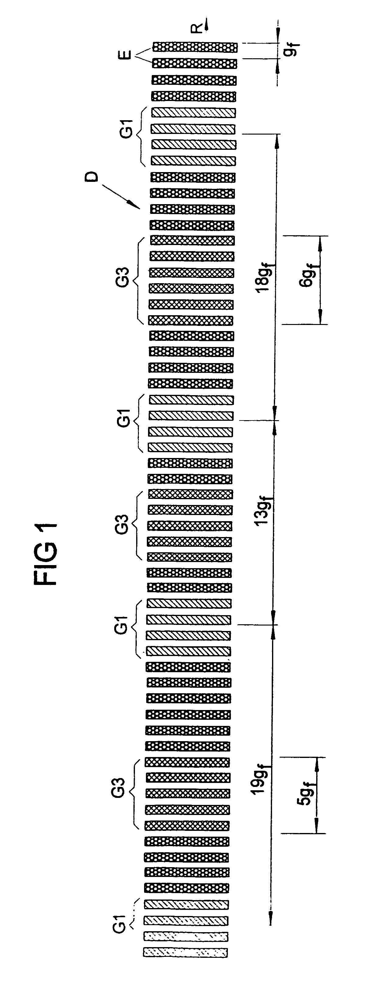
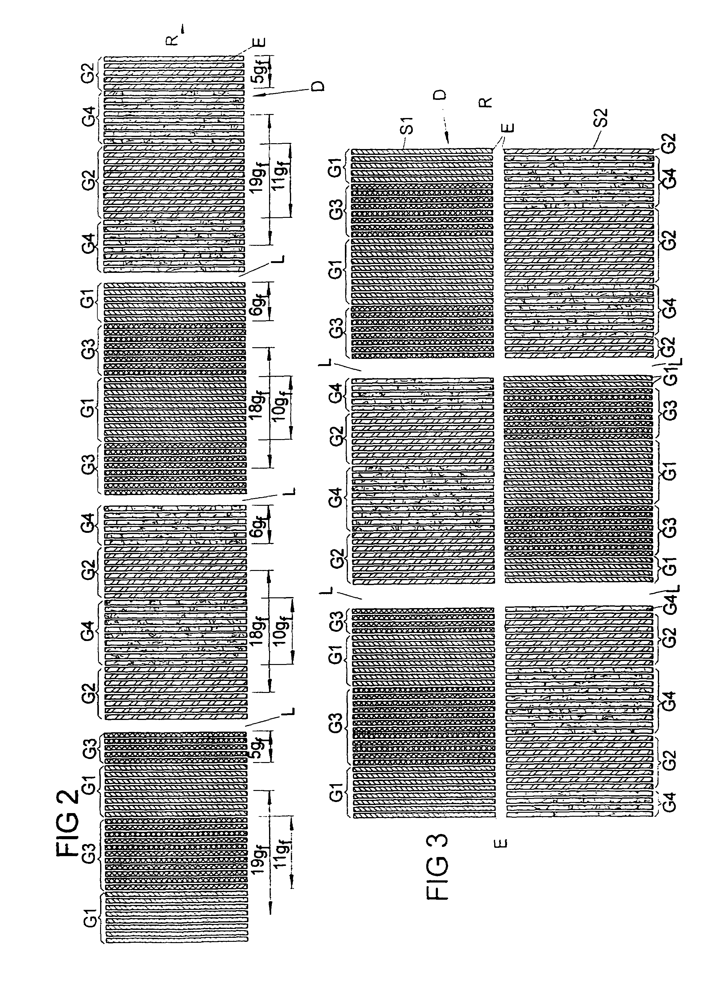
[0008]An example embodiment of the present invention may provide a position-measuring device that may exhibit improved quality of the output signal of the detection device.

Problems solved by technology

However, if for scanning the coarser measuring graduation having the larger grating constant, in each case a plurality of adjacent detector elements are combined to form one detector group, then the output signal generated when scanning the coarser measuring graduation has a significant harmonics component that may interfere in the further processing and evaluation of the output signal.
The distribution of the detector groups, from which signals of one phase are generated, not only along the measuring or extension direction of the detection device, but also on at least two adjacent tracks, may reduce the sensitivity of the arrangement to soiling.
Moreover, in this case the resulting scanning signal may not be influenced by possible changes in the mark width of the scanned measuring graduation.

Method used


Image

  • Position-measuring device including measuring graduation and scanning unit
  • Position-measuring device including measuring graduation and scanning unit
  • Position-measuring device including measuring graduation and scanning unit

Examples


Embodiment Construction

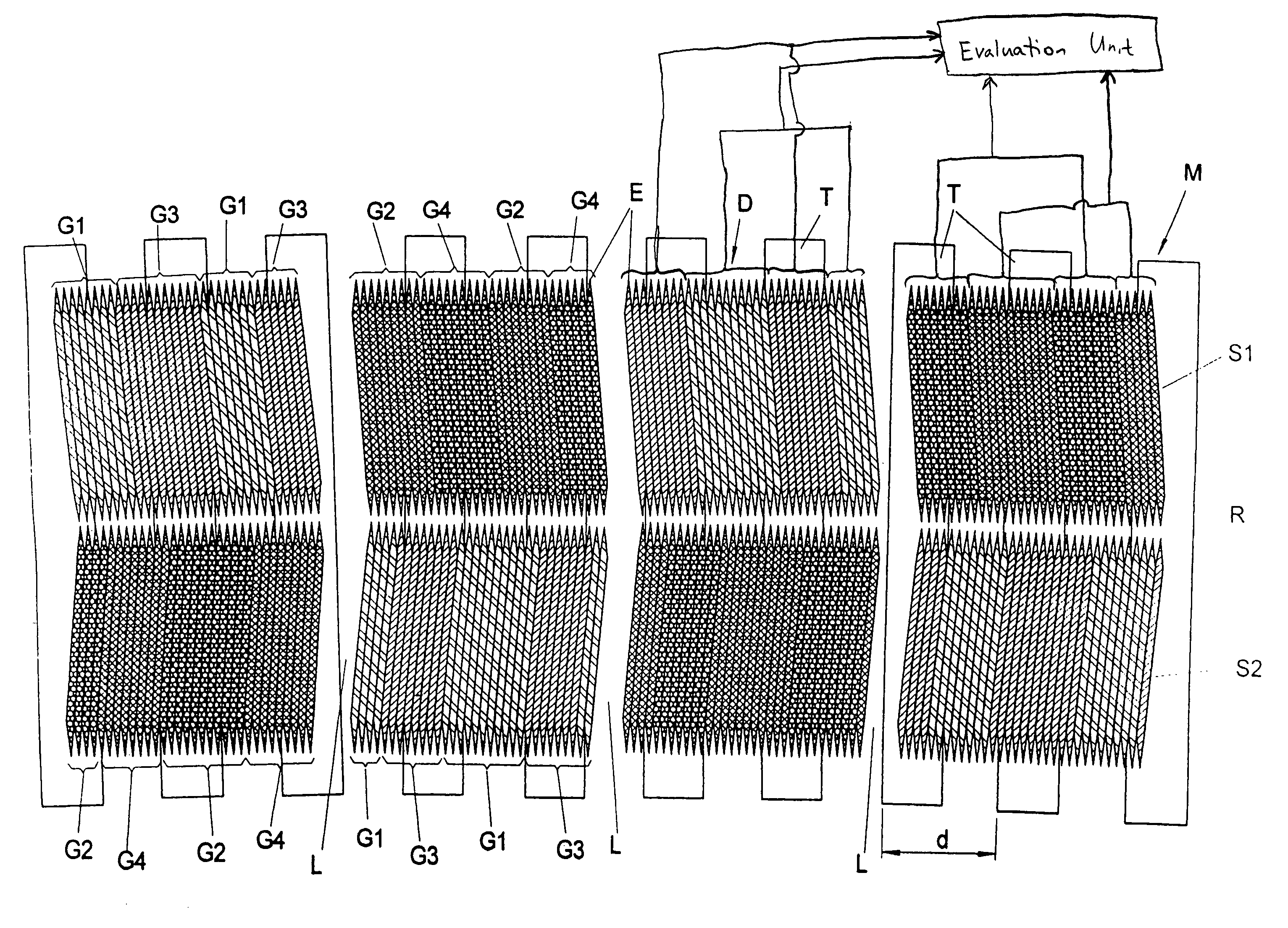
[0068]FIG. 7 schematically illustrates a section of a measuring graduation M of a rotary encoder (angular position-measuring system) which includes a plurality of graduation marks T having a grating constant d and arranged periodically one after the other along extension direction R (defined by a circular arc) of measuring graduation M.

[0069]To scan measuring graduation M having grating constant d, a detector device D of a scanning unit is used which includes a plurality of detector elements E in the form of photo elements that are arranged one after the other in two side-by-side tracks S1, S2 along extension direction R of measuring graduation M.

[0070]Individual detector elements E in the form of photo elements are selected with respect to their size, their arrangement one after the other and their geometry such that, when scanning a measuring graduation of a rotary encoder having a grating constant smaller by fourfold than measuring graduation M illustrated in FIG. 7, generate out...


PUM


Abstract

A position-measuring device includes a measuring graduation extending along a measuring direction, a scanning unit for scanning the measuring graduation, and a detection device of the scanning unit including a plurality of detector elements that are arranged periodically one after the other along an extension direction and that, during scanning of the measuring graduation, generate output signals able to be supplied to an evaluation unit. In each case, a plurality of adjacent detector elements are interconnected to form a detector group such that their output signals are able to be joined and supplied as a unified signal to the evaluation unit. The detector elements are combined to form detector groups, and are arranged in the form of detector groups one after the other along the extension direction such that at least one defined harmonic is eliminated from the output signals.

Description

CROSS-REFERENCE TO RELATED APPLICATIONS[0001]The present application claims priority to Application No. 103 38 991.1, filed in the Federal Republic of Germany on Aug. 18, 2003, which is expressly incorporated herein in its entirety by reference thereto.FIELD OF THE INVENTION[0002]The present invention relates to a position-measuring device and to a scanning unit.BACKGROUND INFORMATION[0003]A position-measuring device of this type includes a linear or curved measuring graduation extending along a measuring direction, a scanning unit for scanning the measuring graduation, as well as a detection device of the scanning unit that includes a plurality of detector elements which are positioned periodically one after the other along an extension direction and which, during the scanning of the measuring graduation, generate output signals able to be supplied to an evaluation unit. In this context, a plurality of adjacent detector elements of the detection device are interconnected to form in...

Claims


Application Information

Patent Timeline
Patent Type & Authority Patents(United States)
IPC IPC(8): G01D5/34G01D5/36G01D5/347
CPCG01D5/34715
Inventor MAYER, ELMAR
Owner DR JOHANNES HEIDENHAIN GMBH
Learn More