Apparatus for shaping a light beam

a technology for shaping apparatus and light beam, which is applied in the direction of light and heating apparatus, instruments, transportation and packaging, etc., can solve the problems of intensity peaks b>19/b>, the inability to use the entire area of optically functional boundary surfaces for shaping laser beams, and the inability to control the intensity of the laser beam

Active Publication Date: 2006-08-01
LIMO GMBH
View PDF14 Cites 58 Cited by
  • Summary
  • Abstract
  • Description
  • Claims
  • Application Information

AI Technical Summary

Benefits of technology

[0015]Furthermore, it is possible to provide that the apparatus has a third and a fourth optically functional boundary surface with imaging elements. In particular, it is possible in this case that arranged on the third and fourth optically functional boundary surfaces are cylindrical lenses whose cylinder axes are parallel to one another and perpendicular to the cylinder axes of the cylindrical lenses on the first and the second optically functional boundary surface. Here, the cylindrical lenses of the third and fourth optically functional boundary surface can furthermore be equipped with two different types of, for example, convex cylindrical lenses in such a way that a superimposition of, for example, component beams passing through concave cylindrical lenses is avoided to the greatest possible extent in the processing plane with regard to the second direction perpendicular to the propagation direction, as well, such that no intensity peaks occur in the intensity distribution in the processing plane with regard to the second direction, either.

Problems solved by technology

It proves to be disadvantageous in this apparatus that the spherical cylindrical lenses are arranged next to one another in such a way as to produce between them a non-defined transition region that either passes or scatters light impinging on it in an uncontrolled fashion.
As a result, the intensity distribution of the laser radiation in the processing plane is disadvantageously influenced, and further it is not possible to use the complete area of the optically functional boundary surfaces for shaping the laser beam.
These outer intensity peaks 19 prove to be extremely disturbing for various applications.

Method used


Image

  • Apparatus for shaping a light beam
  • Apparatus for shaping a light beam
  • Apparatus for shaping a light beam

Examples


Embodiment Construction

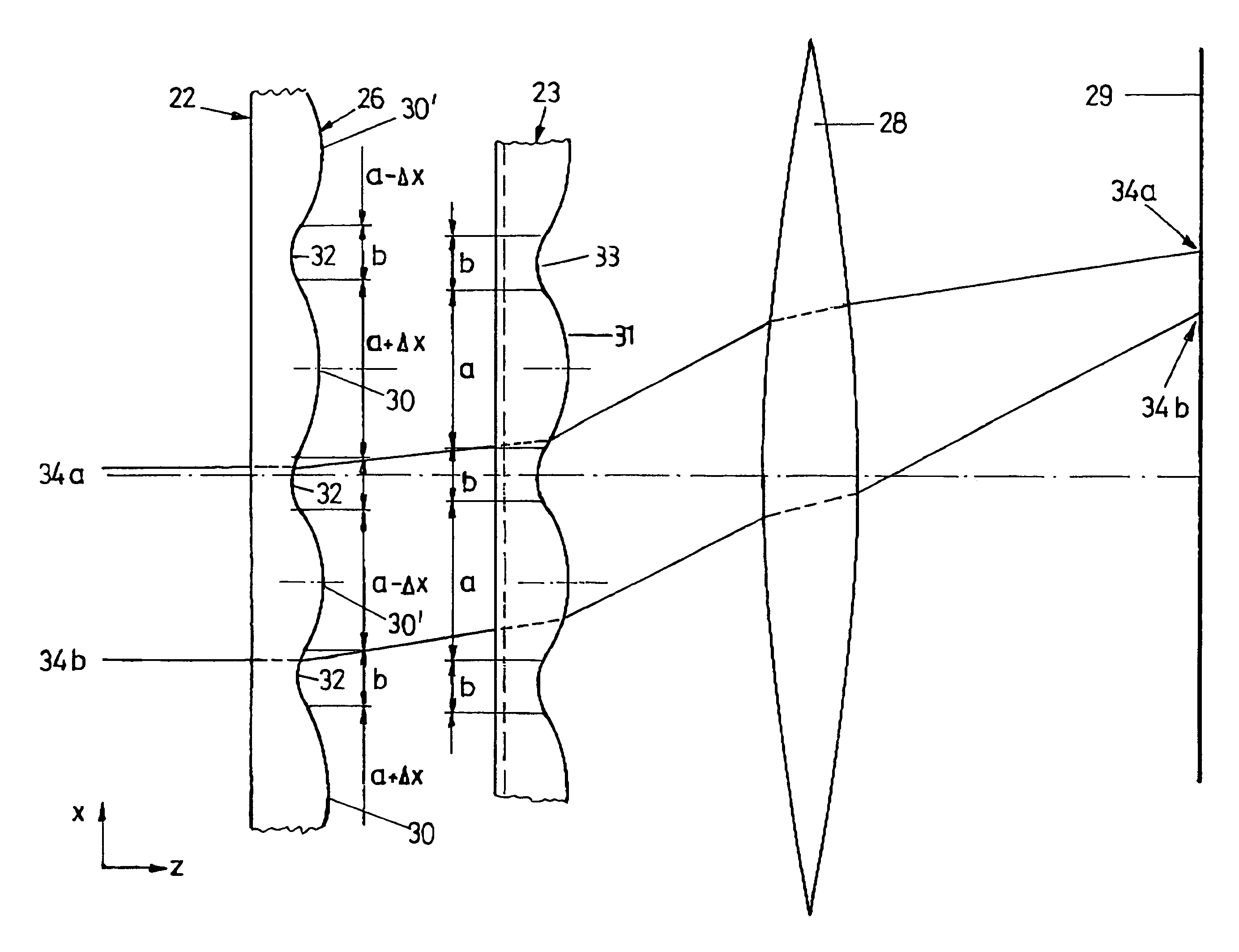
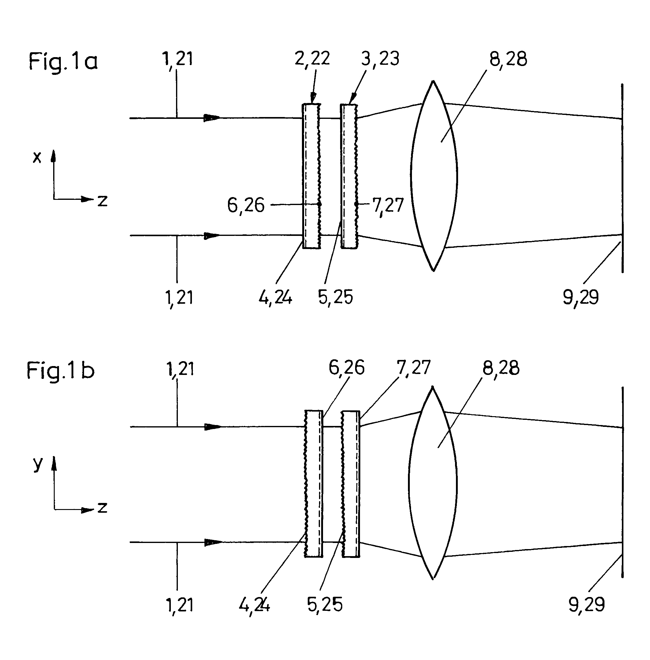
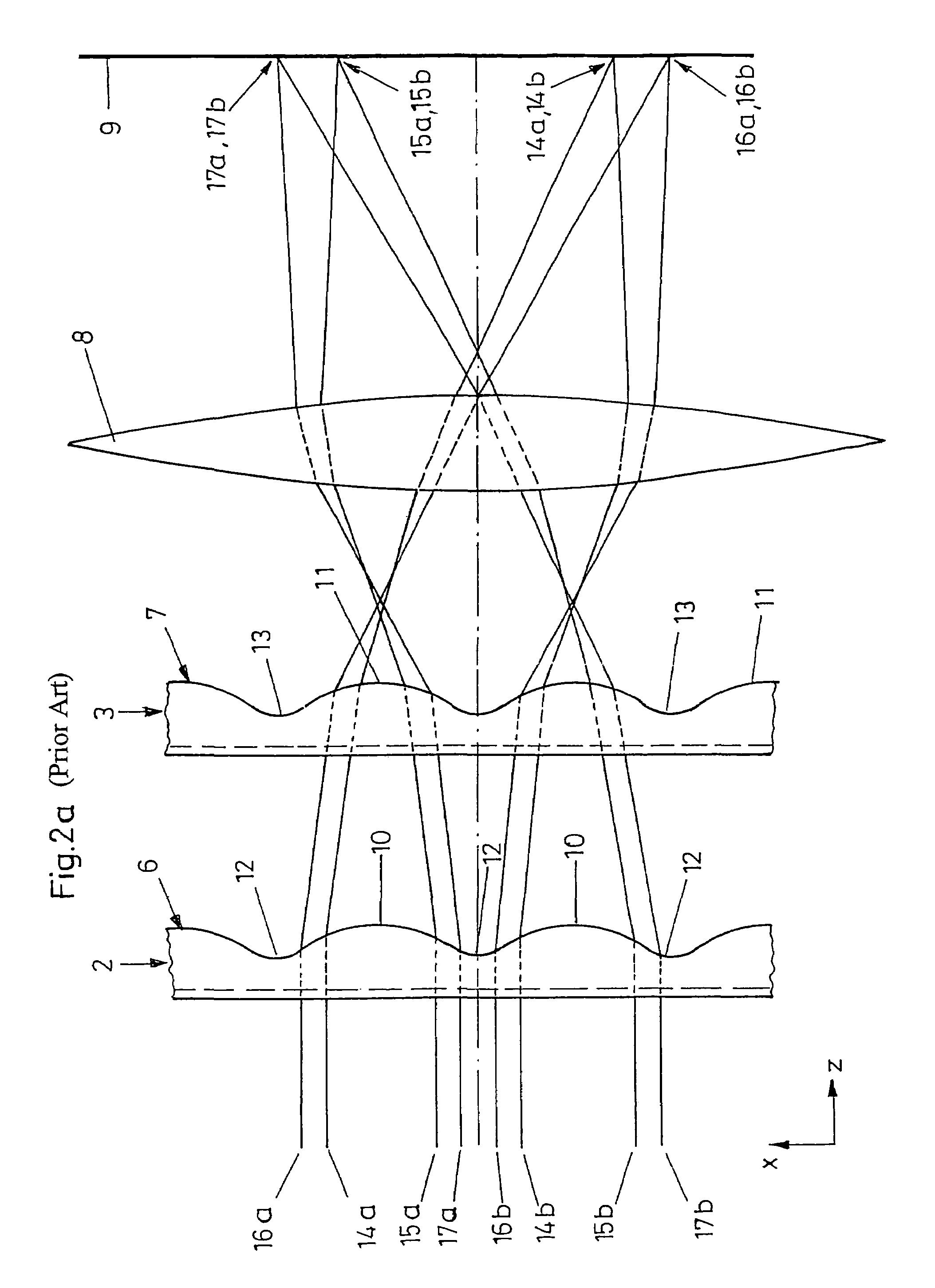
[0024]FIG. 1a and FIG. 1b are schematized in such a way that they can illustrate both the apparatus from the prior art in accordance with FIG. 2a, and an inventive apparatus in accordance with FIG. 3a. The components illustrated in FIG. 1a and FIG. 1b are, firstly, provided with single digit reference numerals 1 to 9 and thereby designate parts that have been explained in the description relating to the prior art in accordance with FIG. 2a. Furthermore, the same parts are provided with double-digit reference numerals 21 to 29, and in this case designate individual parts of the inventive apparatus in accordance with FIG. 3a. In particular, according to the invention in FIG. 1a and FIG. 1b a laser beam 21 runs in the positive Z-direction through lens arrays 22, 23, and is subsequently focused onto an operating plane 25 by a lens means 28 serving as a Fourier lens. In a way similar to the prior art, the lens arrays 22, 23 have optically functional surfaces 24, 25 on the entrance sides,...


PUM


Abstract

The invention relates to an apparatus for shaping a light beam, having at least two optically functional boundary surfaces that are arranged one behind another in the propagation direction (z) of the light beam to be shaped, such that the light beam can pass through the at least two optically functional boundary surfaces one after another, and two groups of refractive or diffractive imaging elements that are arranged on at least one of the optically functional boundary surfaces, at least two of the imaging elements having different properties within at least one of the groups.

Description

BACKGROUND OF THE INVENTION[0001]The present invention relates to an apparatus for shaping a light beam, having at least two optically functional boundary surfaces that are arranged one behind another in the propagation direction of the light beam to be shaped, such that the light beam can pass through the at least two optically functional boundary surfaces one after another, and two groups of refractive or diffractive imaging elements that are arranged on at least one of the optically functional boundary surfaces.[0002]Apparatuses of the abovenamed type are used, for example, for the purpose of homogenizing laser beams, in particular laser beams of excimer lasers. DE 199 15 000 A1, for example, discloses an apparatus for homogenizing an excimer laser beam that has two lens arrays composed of spherical cylindrical lenses. The lens arrays in this case form two optically functionally boundary surfaces, spaced apart from one another, through which the light beam to be shaped can pass o...

Claims


Application Information

Patent Timeline
Patent Type & Authority Patents(United States)
IPC IPC(8): G02B27/10G02B27/42G02B5/18G02B27/46G02B3/06G02B27/09G02B27/44
CPCG02B27/4277G02B27/0944G02B27/09
Inventor HAUSCHILD, DIRK
Owner LIMO GMBH
Why Eureka
Try Eureka