
Apparatus for drying ceramic molded articles using microwave energy

Active Publication Date: 2006-08-08
DENSO CORP +1
View PDF12 Cites 19 Cited by
  • Summary
  • Abstract
  • Description
  • Claims
  • Application Information

AI Technical Summary

Benefits of technology

[0011]The present invention has been developed in view of the problems of the conventional drying apparatus, and the object of the invention is to provide a method and an apparatus for drying ceramic molded articles in which microwave energy is substantially uniformly radiated onto each ceramic molded article charged into the drying chamber and conveyed through the drying chamber, so that the ceramic molded articles are dried with a high quality and free of strains.
[0016]With this drying apparatus, therefore, even in the case where the ceramic molded articles in the drying chamber have different densities, the ceramic molded articles can be irradiated with microwave energy uniformly by controlling the output of the microwave generators, and therefore the ceramic molded articles can be dried substantially uniformly. As a result, the ceramic molded articles maintaining a high accuracy immediately after the extrusion molding process are dried, and through the subsequent baking process, fabricated into ceramic molded articles of high quality.
[0017]In this aspect of the invention, as described above, a drying apparatus is provided in which ceramic molded articles charged into the drying chamber and conveyed through the drying chamber are irradiated uniformly with microwave energy thereby to produce ceramic molded articles of high quality substantially free of strains.
[0024]As described above, in this aspect of the invention, a method of drying ceramic molded articles is provided in which the microwave energy is radiated uniformly on the ceramic molded articles charged into and conveyed through the drying chamber and, therefore, the ceramic molded articles can be dried with a high quality and substantially free of strains.

Problems solved by technology

This conventional drying apparatus poses the problem described below.
Specifically, in the case where the ceramic molded articles are arranged at irregular intervals in the drying chamber of the drying apparatus, the amount of microwave energy absorbed into the ceramic molded articles lacks uniformity.
Especially in the case where the train of ceramic molded articles in the drying chamber is temporarily disconnected, the neighboring ceramic molded articles may be overdried by absorbing an increased amount of microwave energy.

Method used


Image

  • Apparatus for drying ceramic molded articles using microwave energy
  • Apparatus for drying ceramic molded articles using microwave energy
  • Apparatus for drying ceramic molded articles using microwave energy

Examples


first embodiment

(First Embodiment)

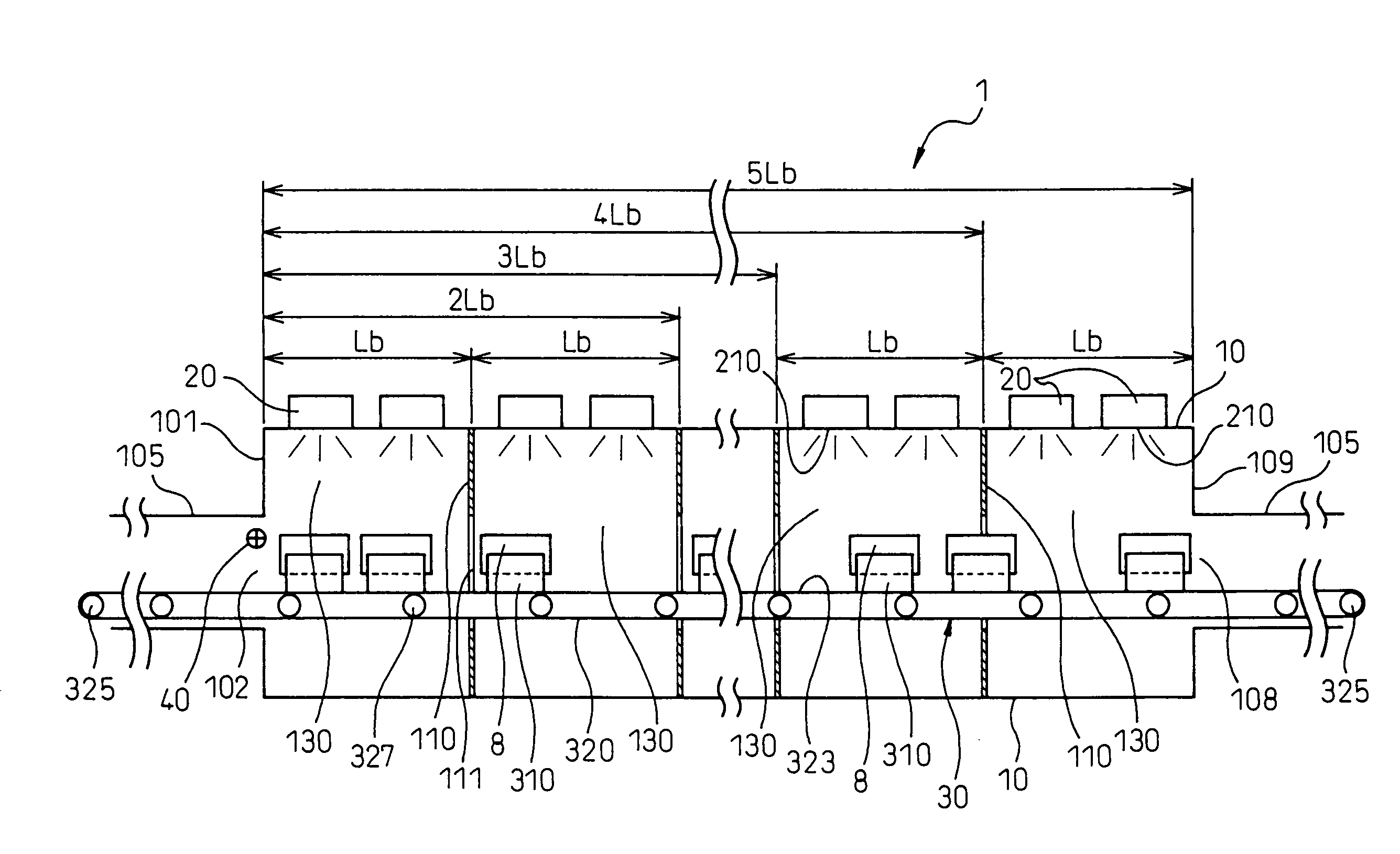
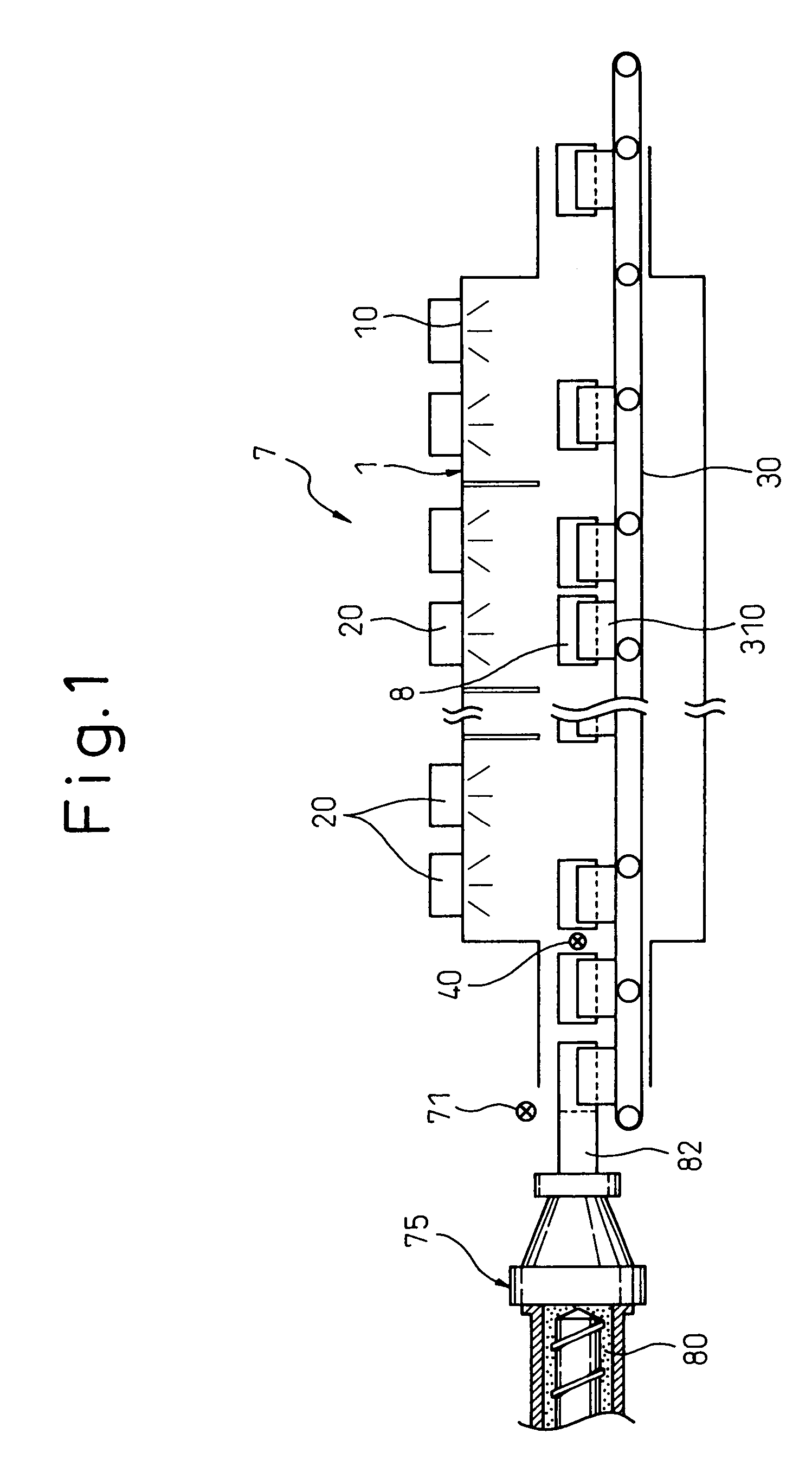
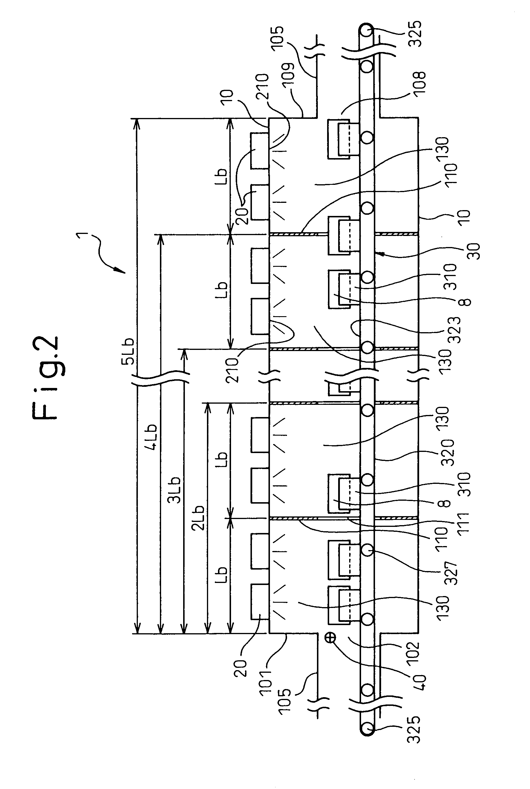
[0040]A drying apparatus for ceramic molded articles according to an embodiment of the invention is explained with reference to FIGS. 1 to 5.

[0041]A drying apparatus 1 according to this embodiment, as shown in FIG. 2, comprises a drying chamber 10 for accommodating a plurality of ceramic molded articles 8 (FIG. 4), a plurality of microwave generators 20 for supplying the microwave energy in the frequency range of 300 MHz to 300 GHz into the drying chamber 10, and a conveyor 30 whereby the ceramic molded articles 8 are continuously charged into, conveyed through and delivered out of the drying chamber 10.

[0042]The drying chamber 10 has arranged therein a plurality of microwave generators 20 along the direction of conveyance of the conveyor 30, and a sensor 40 for detecting the distribution of the ceramic molded articles 8 in the drying chamber 10.

[0043]The output of each microwave generator 20 is adapted to be changed in accordance with the distribution of the ceram...

second embodiment

(Second Embodiment)

[0111]According to this embodiment, a plurality of drying areas adapted to move with the operation of the conveyor are formed in place of the drying blocks fixedly arranged in the drying chamber in the first embodiment.

[0112]In this embodiment, as shown in FIG. 10, a plurality of reflectors 345 for reflecting the microwave energy are mounted on a part of the rests in place of the partitioning walls of the drying chamber according to the first embodiment. The reflectors 345 make up drying areas 340 in the drying chamber 10. Also, the ceramic molded articles 8 placed on the rests are set vertically instead of horizontally.

[0113]This embodiment is specifically described below.

[0114]In the drying apparatus 1 according to this embodiment, a substantially tabular reflector 345 for reflecting the microwave energy is mounted substantially at right angles to the direction of conveyance at the end portion of each of at least a part of the rests along the direction of convey...

third embodiment

(Third Embodiment)

[0158]This embodiment concerns a case in which at least a radio wave absorber is arranged on the inner wall of the drying chamber in place of the partitioning walls limiting the range of microwave energy radiation in the drying apparatus according to the first embodiment.

[0159]In the drying apparatus 1 according to this embodiment, as shown in FIG. 13, a plurality of radio wave absorbers 440 are attached on the inner wall of the drying chamber 10. The radio wave absorbers 440 limit the range of microwave radiation for each microwave generator 20.

[0160]Specifically, in the drying chamber 10 with the radio wave absorbers 440 attached on the inner wall thereof, the microwave supplied into the drying chamber 10 is less likely to reach a distant point by being repeatedly reflected. With this drying chamber 10, as shown in FIG. 12, the microwave energy constituting a direct wave generated from the microwave generators can dry the ceramic molded articles 8.

[0161]According...


PUM

PropertyMeasurementUnit
Frequencyaaaaaaaaaa
Frequencyaaaaaaaaaa
Angleaaaaaaaaaa

Abstract

An apparatus and a method, for drying ceramic molded articles, are disclosed. A drying apparatus (1) comprises a drying chamber (10) for accommodating ceramic molded articles (8), a plurality of microwave generators (20) for supplying microwave energy into the drying chamber, and a conveyor (30) for charging the ceramic molded articles (8) continuously into the drying chamber (10), conveying the ceramic molded articles through the drying chamber, and delivering the ceramic molded articles from the drying chamber. The drying chamber (10) has arranged therein a plurality of the microwave generators (20) and at least a sensor (40) for detecting the distribution of the ceramic molded articles (8) in the drying chamber (10). Each microwave generator (20) is adapted to change the output thereof in accordance with the distribution of the ceramic molded articles (8) detected by the sensor (40).

Description

BACKGROUND OF THE INVENTION[0001]1. Field of the Invention[0002]The present invention relates to a method and an apparatus for drying ceramic articles molded by extrusion.[0003]2. Description of the Related Art[0004]In fabricating ceramic molded articles, a clay-like ceramic material is extruded, dried and baked.[0005]A conventional apparatus for drying ceramic molded articles is disclosed, for example, in JPP (Japanese Unexamined Patent Publication) 2000-44326, in which a part of the path for conveying extruded ceramic molded articles is covered by a drying chamber, and the ceramic molded articles being conveyed through the drying chamber are dried by being irradiated with microwave energy.[0006]In this conventional drying apparatus, the microwave energy is required to be slowly and uniformly radiated in order to dry the ceramic molded articles uniformly without any strain. For this purpose, it is common practice to carry out the drying process in which a plurality of ceramic molde...

Claims


Application Information

Patent Timeline
IPC IPC(8): H05B6/68H05B6/78B28B3/20C04B33/30B28B11/00B28B11/24C04B35/64F26B3/347F26B15/12F26B25/00
CPCB28B3/206B28B11/241B28B11/243C04B35/62655F26B3/347F26B15/12F26B25/003H05B6/78B28B2003/203H05B2206/046C04B2235/94C04B2235/6021
Inventor ISHIKAWA, SATOSHIKATOU, HIROMIGOTO, SHOICHIMINOBE, TOMIO
Owner DENSO CORP
Learn More