Balanced magnetic linear displacement sensor

a linear displacement and magnetic field technology, applied in the field of magnetic sensors, can solve the problems of reducing the linearity of the detected sensor output, increasing the additional signal processing overhead required to linearize the detected output, and system failures

Active Publication Date: 2006-08-08
SENSATA TECHNOLOGIES INC
View PDF12 Cites 83 Cited by
  • Summary
  • Abstract
  • Description
  • Claims
  • Application Information

AI Technical Summary

Benefits of technology

[0011]The following summary of the invention is provided to facilitate an understanding of some of the innovative features unique to the present invention and is not intended t

Problems solved by technology

This is a benefit because over time contacts can degrade and cause system failures.
The non-linear transducer response from Hall element 2 is detrimental in practice, resulting in reduced detected sensor output linearity and increased additional signal processing overhead required to linearize the detected output.
This non-linearit

Method used


Image

  • Balanced magnetic linear displacement sensor
  • Balanced magnetic linear displacement sensor
  • Balanced magnetic linear displacement sensor

Examples


Embodiment Construction

[0026]The present invention is described in a preferred embodiment in the following description with reference to the figures. While this invention is described in terms of the best mode for achieving this invention's objectives, it will be appreciated by those skilled in the art that variations may be accomplished in view of these teachings without deviating from the spirit or scope of the present invention.

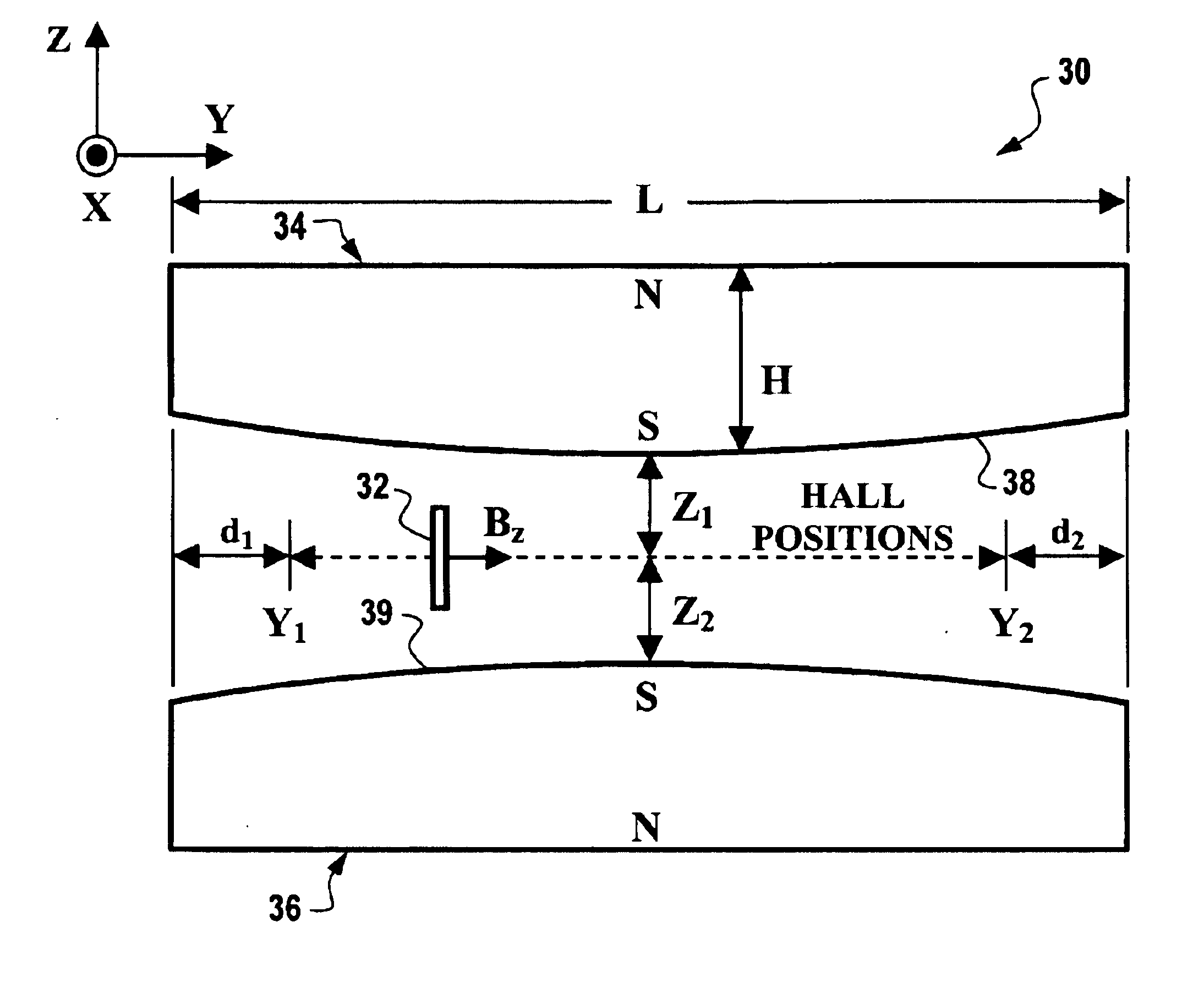
[0027]The present invention is directed to a magnetic linear displacement sensor device and system incorporating the same that provide a substantially linear Hall response output while minimizing output response errors caused by manufacturing and assembly tolerances and variations. More specifically, and as explained in further detail with reference to the figures, the present invention employs a Hall-type transducer element in combination with one or more magnets having contouring and polarization characteristics enabling the Hall element to detect a substantially linear orthog...


PUM


Abstract

A magnetic linear displacement sensor. In accordance with one embodiment, the displacement sensor includes a Hall transducer element having a sensor plate surface and at least one magnet having a lengthwise dimension along which said Hall element detects a magnetic field component orthogonal to the sensor plate surface during displacement sensing. The magnet includes first and second pole faces disposed on opposite lengthwise sides thereof and a polarization axis aligned orthogonally with respect to the lengthwise dimension. The first pole face opposes the Hall, element and is characterized as having a non-planar surface contoured to generate a substantially linear orthogonal magnetic field component sensed by said Hall element during linear displacement sensing.

Description

TECHNICAL FIELD[0001]Embodiments are generally related to a magnetic sensor for detecting and tracking the relative position of a target object. The embodiments are also related to a magnetic sensor configured to provide a linear magneto-electric response while optimally compensating for sensor alignment placement tolerances.BACKGROUND OF THE INVENTION[0002]Magnetic sensing devices have many detection applications, including navigation, current sensing, and linear and angular position and displacement sensing. Magnetic sensors provide a non-contacting means for determining position related parameters such as shaft rotation, presence of magnetic ink, vehicle heading, etc. One of the benefits of using magnetic sensors is that the output of the sensor is generated without the use of contacts. This is a benefit because over time contacts can degrade and cause system failures.[0003]A Hall sensor is a common magnetic sensor type having many applications including detection of the linear d...

Claims


Application Information

Patent Timeline
IPC IPC(8): G01B7/00G01B7/02G01D5/14
CPCG01D5/145G01D2205/18
Inventor BUSCH, NICHOLAS F.
Owner SENSATA TECHNOLOGIES INC
Why Eureka
Try Eureka