
Method of operating a display system in a vehicle for finding a parking place

a display system and vehicle technology, applied in the field of vehicle operation, can solve the problems of high cost of providing the required system of distance sensors, damage that can easily occur to other vehicles or to the driver's own vehicles, and it is impossible to reliably guarantee the correspondence between the actual starting position and the starting position. , to achieve the effect of facilitating the interpretation of images displayed on the display screen, reducing recognizability, and good orientation aid

Active Publication Date: 2006-08-08
DONNELLY HOHE GMBH & CO KG
View PDF11 Cites 35 Cited by
  • Summary
  • Abstract
  • Description
  • Claims
  • Application Information

AI Technical Summary

Benefits of technology

[0011]Inasmuch as a control and / or regulating device is provided in the vehicle controller so that steering instructions, in particular steering angle settings, can be calculated automatically on the basis of the parking situations selected by the user, then the data thus obtained for describing the size and position of the actual parking place can also be taken into account in calculating the steering instructions. As a result, steering instructions coordinated with the current parking place situation can be calculated and provided to the driver without requiring any separate measurement sensors to measure the parking place situation.
[0012]To be able to represent the largest possible range of observation in the environment of the vehicle it is especially advantageous if the image data of several cameras can be combined in the image processing unit and superimposed on an image to be displayed jointly on the display screen. For example, it is conceivable for two video cameras, in particular CCD cameras, to be arranged on the trunk of the vehicle, where one camera observes the area at the center and to the left of the center and the other camera observes the area at the center and to the right of center. The image data of the two cameras may then be combined to permit a display of a single image with a correspondingly enlarged observation area.
[0017]With the method according to this invention, the driver can position his vehicle in such a way that he can reliably drive into a parking place situated in an ambient area. In particular, he can evaluate reliably through the method according to this invention whether the size of an available parking place is sufficient for parking his own vehicle. However, this alone is often not sufficient to prevent collisions because in parking in a parking place starting from the starting position, the vehicle passes over certain areas where collision obstacles may be located. Therefore, according to a preferred embodiment, a driving movement symbol, e.g., a driving tube symbolizing the area in which there must not be any objects to collide with because this area is crossed over when parking to reach the area symbolized by the parking place symbol, is superimposed on the image. In this way, the driver is given an opportunity in a very simple manner to check on whether objects picked up by the camera in the ambient area are situated in the driving path in the planned parking operation and could thus lead to collisions.

Problems solved by technology

One disadvantage of this known method is the extremely high cost of providing the required system of distance sensors which is necessary to be able to reliably measure the size of the parking place.
In addition, there are a number of product liability issues with this system because if errors occur due to the measurement by the distance sensors, damage can easily occur to other vehicles or to the driver's own vehicle.
However, this support system functions satisfactorily only when the actual starting position of the vehicle corresponds to the starting position of the vehicle stored temporarily in this scenery.
One disadvantage of this system is that it is impossible to reliably guarantee a correspondence between the actual starting position and the starting position stored temporarily in the scenery that is actually sufficiently accurate.

Method used


Image

  • Method of operating a display system in a vehicle for finding a parking place
  • Method of operating a display system in a vehicle for finding a parking place
  • Method of operating a display system in a vehicle for finding a parking place

Examples


Embodiment Construction

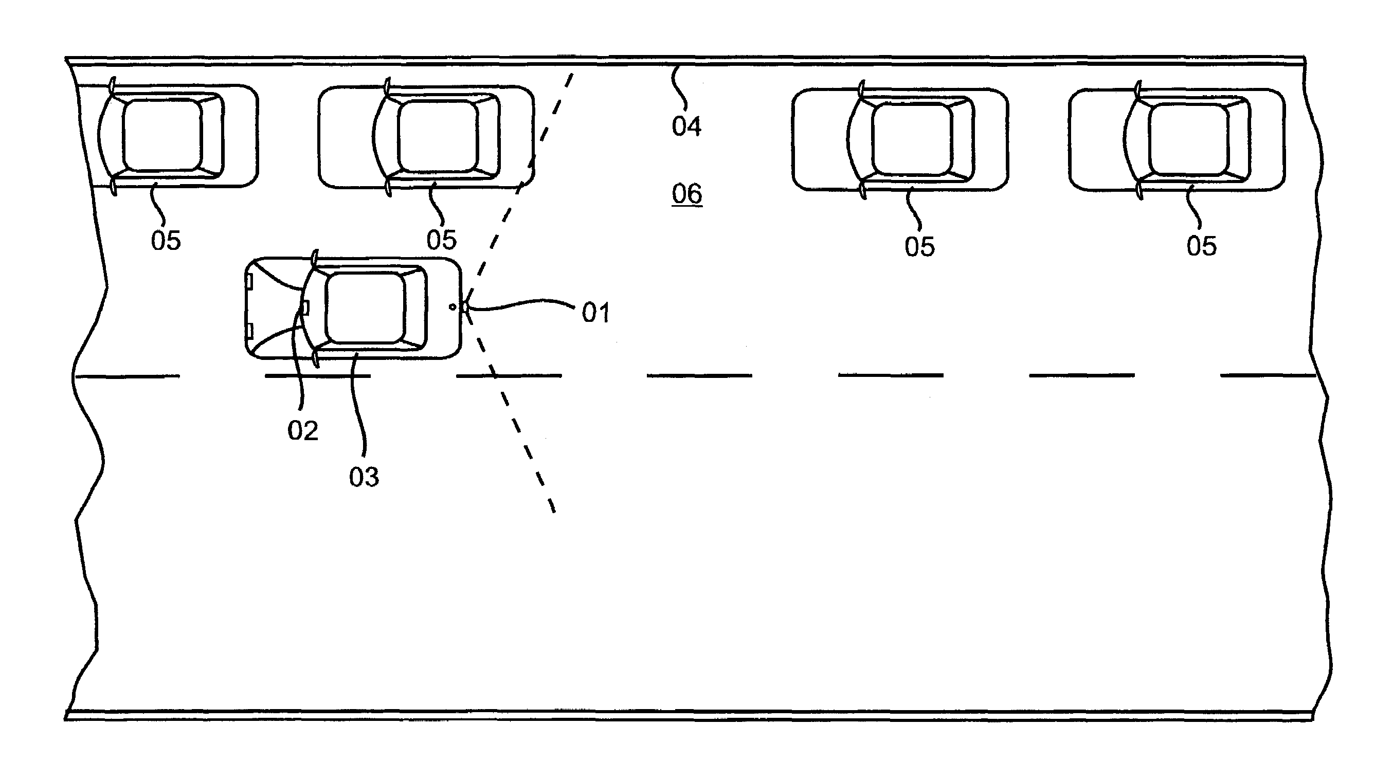
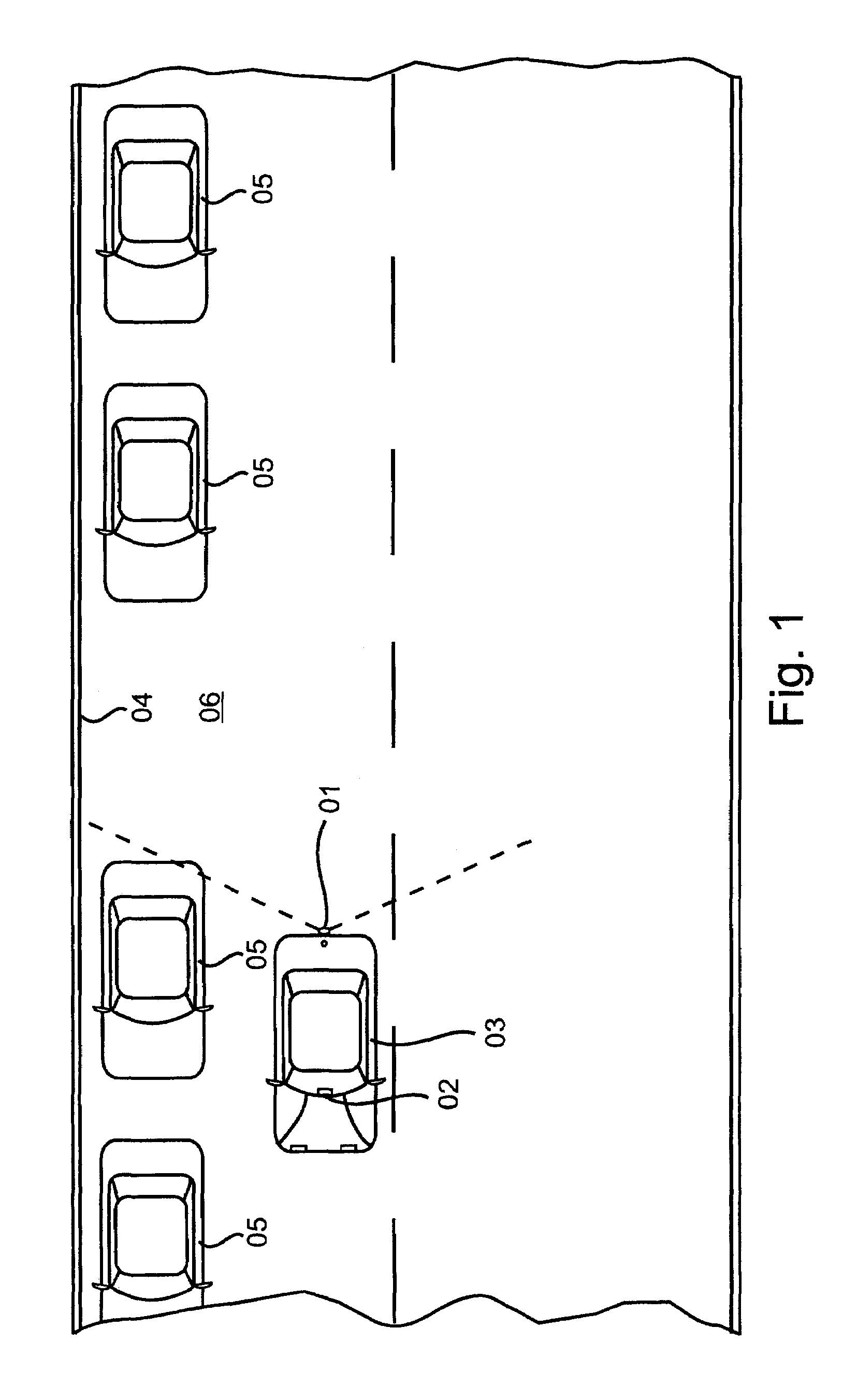
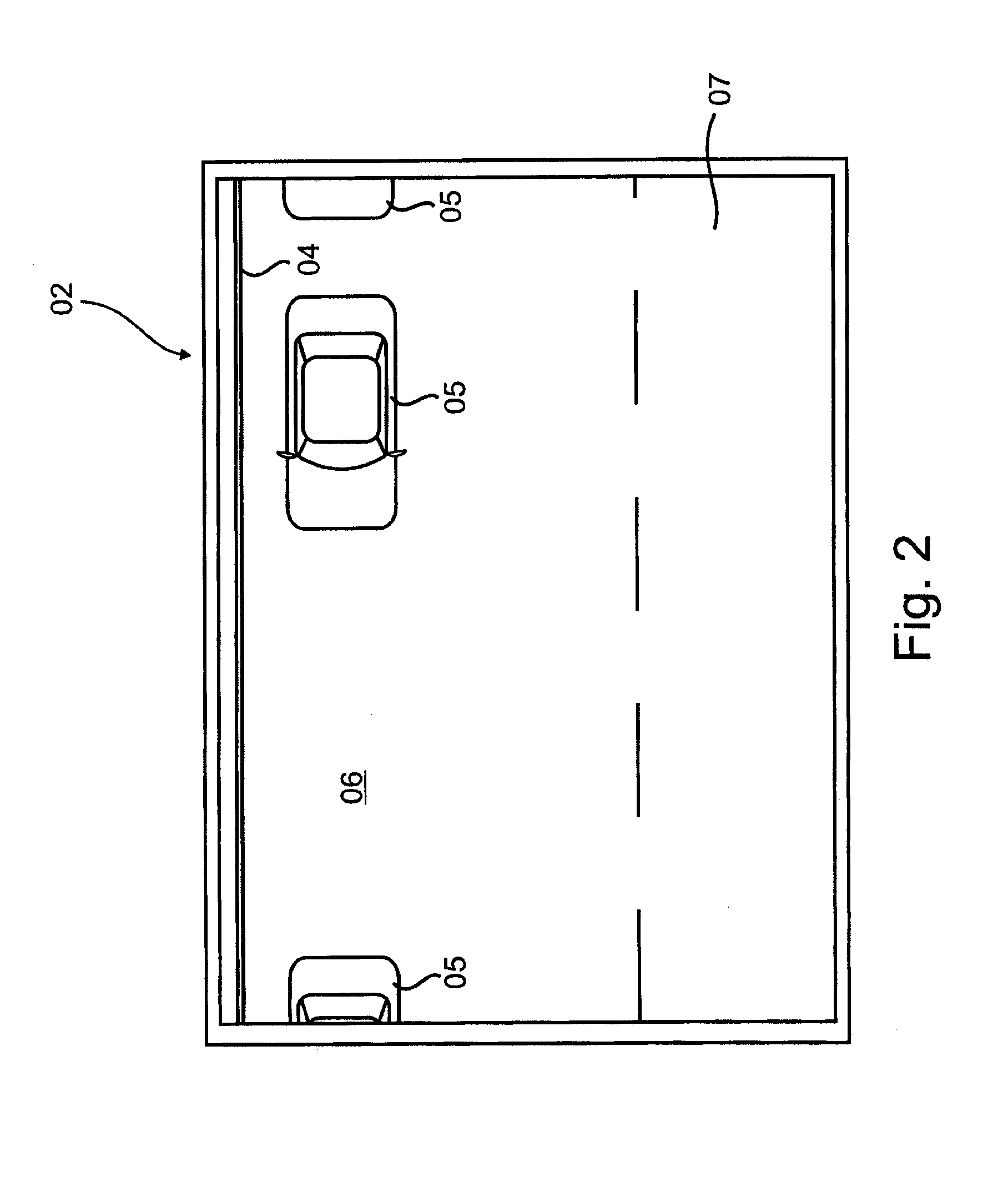
[0031]Referring to the drawings in particular, FIG. 1 shows a schematic diagram of a typical parking situation. A vehicle 03 equipped with a suitable display system with a camera 01 and a display screen 02 drives past a row of vehicles 05 parking parallel to the curb 04 and is searching for a parking place 06 where the vehicle 03 can be parked. With camera 01 the ambient area behind the trunk of vehicle 03 is recorded and displayed as a live image on display screen 02. By processing the image data in an image processing unit (not shown) in the vehicle 03, the image data coining from the camera 01 are converted so that distortion caused by a wide-angle lens provided on the camera 01 is eliminated, and at the same time the display on the display screen 02 corresponds to a perspective in a an overhead view as seen from above the vehicle 03.

[0032]FIG. 2 shows the display screen 02 on which an image 07 is displayed, recorded by camera 01 at the time according to FIG. 1 and converted by t...


PUM


Abstract

A method of operating a display system in a vehicle (03) for finding a suitable parking place (06) with at least one camera (01) with which an observation area in the vicinity of the vehicle (03) can be recorded, with an image processing unit in which the image data coming from a camera (03) can be processed and a display screen (02) in the interior of the vehicle on which the image data coming from the image processing unit can be displayed as an image (07). A parking place symbol (08, 18, 20) is superimposed by the image processing unit on the current image (07) on the display screen (02), symbolizing true to scale an area in the current image (07) which the vehicle (03) can reach in parking, starting from its current position, taking into account the properties of the vehicle, in particular the size of the vehicle and the maximum steering angle.

Description

FIELD OF THE INVENTION[0001]This invention relates to a method of operating a display system in a vehicle for finding a suitable parking place the system having a camera, an image processing unit and a display screen in the interior of the vehicle.BACKGROUND OF THE INVENTION[0002]Various approaches for supporting the driver of a vehicle in parking are known from the state of the art.[0003]German Patent DE 100 45 616 A1 describes a method of operating a display system according to the preamble of Claim 1. In this method, distance sensors are additionally provided for measuring the parking place. Based on these measured data, the controller then evaluates whether the parking place is sufficient for parking the vehicle. If this is the case, a parking strategy is calculated automatically so that the vehicle can be steered into the parking place. One disadvantage of this known method is the extremely high cost of providing the required system of distance sensors which is necessary to be ...

Claims


Application Information

Patent Timeline
IPC IPC(8): G08G1/14G08G1/00B60Q1/48B60R1/00B62D15/02G08G1/16
CPCB60Q9/005B60R1/00G08G1/161B62D15/028B60R2300/105B60R2300/302B60R2300/305B60R2300/806B60R2300/8086B60T2201/10B60R2300/607B60R1/26
Inventor SCHINDLER, BENNO TOBIASWEIS, TIM
Owner DONNELLY HOHE GMBH & CO KG
Learn More