Imaging apparatus in which exposure control is performed to suppress changes in sensitivity due to changes in gradation mode

a technology of exposure control and exposure control, applied in the field of imaging apparatus, can solve the problems of large changes in output level, inability to obtain an equal output level over a whole luminance distribution of the photographic subject, and inability to achieve the effect of sensitivity and output level

Inactive Publication Date: 2006-08-08
OLYMPUS OPTICAL CO LTD +1
View PDF10 Cites 27 Cited by
  • Summary
  • Abstract
  • Description
  • Claims
  • Application Information

AI Technical Summary

Benefits of technology

[0024]An object of the present invention is to provide an imaging apparatus which can hold sensitivity and output level to be constant even when a gradation property is changed.
[0025]Moreover, another object of the present invention is to provide an imaging apparatus in which imaging with an enhanced sensitivity can be carried out by addition of pixel information in an analog adding system, and an image quality can be prevented from being deteriorated by clip in an A / D converter.
[0065]Moreover, the cross point is a point corresponding to 18 to 20% (±⅓ EV) of an input full scale. This value is in the vicinity of a logarithmic midpoint of a photographic subject range, and an region with a maximum possibility of correspondence to a main photographic subject is in the vicinity of the logarithmic midpoint of the photographic subject range. Therefore, the value can be the to be a best selection. Furthermore, the knee property is disposed so that the range is ensured with the intersecting of the properties. Thereby, a photographic subject reproduction range can be prevented from being narrowed with a large gamma.
[0072]According to the present invention, the quantized level setting means variably sets the quantized maximum level in the A / D converting means in accordance with the added number of adding / reading by the driving means. Thereby, a phenomenon in which the A / D input voltage exceeds the A / D quantized maximum voltage with the signal addition can be suppressed. Therefore, the added signal can be prevented beforehand from being clipped by the A / D converting means. Therefore, photography with enhanced sensitivity is enabled by addition of the pixel information of the analog adding system without deteriorating the image quality by the clip in the A / D converting means.

Problems solved by technology

Therefore, a problem is that the obtained output level changes.
Since the gradation property is changed, it is originally impossible to obtain an equal output level over a whole luminance distribution of the photographic subject.
Additionally, in the conventional digital camera, since these are not considered, the output level disadvantageously changes largely as described above.
Additionally, when this technique is actually applied to the electronic camera, the sensitivity can be enhanced, but a noise increases with the sensitivity enhancement.
Beyond simple resolution deterioration because of a decrease of the number of pixels, image quality deterioration further occurs.
However, this cannot be said to be correct in consideration about the noise.
Therefore, during imaging while the image quality, that is, the noise level is kept, the imaging with double sensitivity, that is, ½ of the standard exposure amount is a limitation.
In an analog adding system in the digital camera, there is a problem of saturation in an A / D converter.
However, in a usual non-addition time, the maximum value of CCD output signal is Dmax / 2, and a larger digital bit is wasted.
In other words, a relative quantized error disadvantageously becomes double from an ideal state.
In other words, the A / D converter with a larger number of bits than an originally necessary number of bits is necessary, and cost increase is unfavorably caused.
There is a problem that the image quality is deteriorated.

Method used


Image

  • Imaging apparatus in which exposure control is performed to suppress changes in sensitivity due to changes in gradation mode
  • Imaging apparatus in which exposure control is performed to suppress changes in sensitivity due to changes in gradation mode
  • Imaging apparatus in which exposure control is performed to suppress changes in sensitivity due to changes in gradation mode

Examples


Embodiment Construction

[0082]A detail of a digital camera according to an embodiment of the present invention will be described hereinafter with reference to the drawings.

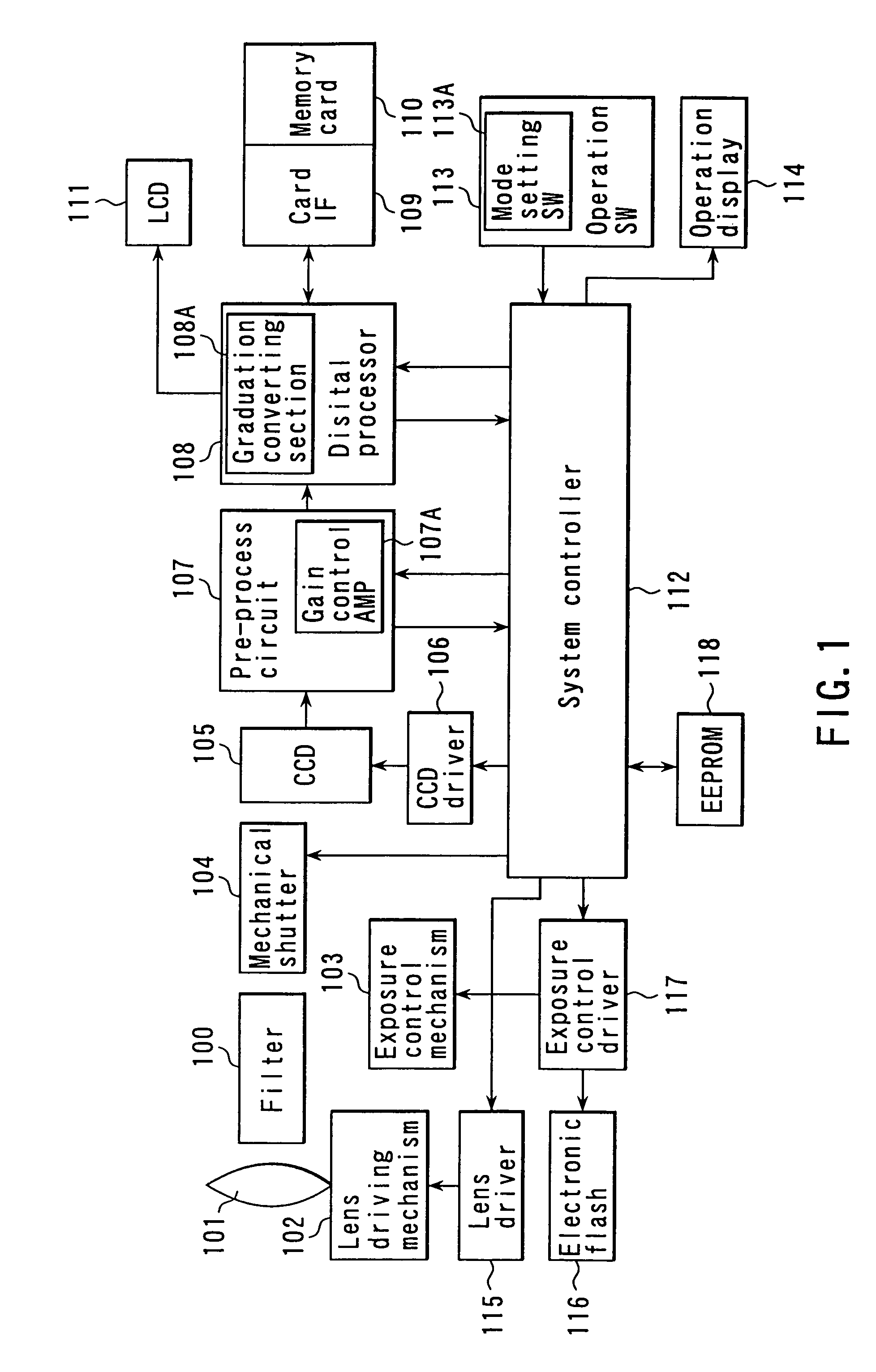
[0083]FIG. 1 is a block diagram showing a circuit configuration of the digital camera according to one embodiment of the present invention. In FIG. 1, reference numeral 101 denotes a photography lens system constituted of various lenses for photographing a photographic subject, 102 denotes a lens driving mechanism for driving the lens system 101 in accordance with the photographic subject, and the lens driving mechanism 102 drives the photography lens system 101 to focus the photography lens system 101 on the photographic subject. Light rays reflected from the photographic subject are directed to CCD unit 105 via the lens system 101 and a stop included in an exposure control mechanism 103. In the exposure control mechanism 103, the stop is adjusted, the light rays passed through the stop is controlled and an exposure amount is controlled...


PUM


Abstract

A digital camera which can change gradation properties comprises a CCD image pickup element 105 for photographing a subject, an exposure control mechanism 103 for controlling an exposure on the image pickup element 105, a digital processing circuit 108 including a gradation converting circuit for being capable of generating image signals having different gradation properties (gamma properties) based on the output signal from the image pickup element 105, and a system controller 112 including a selecting circuit for selecting one of the different gradation properties, which is used in the gradation converting circuit. In the digital camera, to suppress the change of a sensitivity (output level) due to the a change of the gradation property, the exposure control mechanism 103 changes a control target value to control the exposure in accordance with the selected gamma value so that the output level is maintained at constant in the average exposure.

Description

CROSS-REFERENCE TO RELATED APPLICATIONS[0001]This application is based upon and claims the benefit of priority from the prior Japanese Patent Applications No. 2000-183310, filed Jun. 19, 2000, No. 2000-188030, filed Jun. 22, 2000, and No. 2000-188031, filed Jun. 22, 2000, the entire contents of which are incorporated herein by reference.BACKGROUND OF THE INVENTION[0002]1. Field of the Invention[0003]The present invention relates to an imaging apparatus in which a gradation (gamma: γ) property (gradation property curve) can be changed, and particularly to an imaging apparatus in which the gradation property can be changed and exposure control is improved.[0004]Moreover, the present invention relates to an imaging apparatus in which an image pickup device such as CCD is incorporated, and particularly to an imaging apparatus in which sensitivity is enhanced by addition of pixels.[0005]2. Description of the Related Art[0006]In recent years, an imaging apparatus has intensively been deve...

Claims


Application Information

Patent Timeline
Patent Type & Authority Patents(United States)
IPC IPC(8): H04N5/202H04N1/407H04N5/235H04N5/351
CPCH04N1/407H04N5/2352H04N5/202H04N23/72
Inventor MORI, KEIICHIYOSHIDA, HIDEAKI
Owner OLYMPUS OPTICAL CO LTD
Why Eureka
Try Eureka