Region extraction in vector images

a vector image and region extraction technology, applied in image data processing, television systems, instruments, etc., can solve the problems of difficult automation of this process on a computer, inability to accurately track objects with multiple components with non-rigid motion, and difficulty in achieving the effect of improving the accuracy of the tracking method

Inactive Publication Date: 2006-08-08
MICROSOFT TECH LICENSING LLC
View PDF97 Cites 55 Cited by
  • Summary
  • Abstract
  • Description
  • Claims
  • Application Information

AI Technical Summary

Benefits of technology

[0018]Implementations of the method include other features to improve the accuracy of the tracking method. For example, the tracking method preferably includes region-based preprocessing to remove image errors without blurring object boundaries, and post-processing on the computed semantic object boundaries. The computed boundary of an object is formed from the individual regions that are classified as being associated with the same semantic object in the target frame. In one implementation, a post processor smooths the boundary of a semantic object using a majority operator filter. This filter examines neighboring image points for each point in a frame and determines the semantic object that contains the maximum number of these points. It then assigns the point to the semantic object containing the maximum number of points.

Problems solved by technology

Extracting a semantic video object from a video clip has remained a challenging task for many years.
While semantic objects are easy for viewers to discern, the wide variety of shapes, colors and motion of semantic objects make it difficult to automate this process on a computer.
While a great deal of research has focused on object tracking, existing methods still do not accurately track objects having multiple components with non-rigid motion.
The major drawback of these forward techniques lies in the difficulty of either assembling / adjusting the projected regions in the current frame or dealing with multiple non-rigid motions.
In many of these cases, uncertain holes may appear or the resulting boundaries may become distorted.
Methods that assume that objects are formed of connected groups of pixels do not track these types of disconnected objects well.
Methods that assume an object has homogenous motion do not track these types of objects well.
Since object tracking methods typically partition each frame based on a previous frame's partition, errors in the previous frame tend to get propagated to the next frame.
Unless the tracking method computes an object's boundary with pixel-wise accuracy, it will likely propagate significant errors to the next frame.
As result, the object boundaries computed for each frame are not precise, and the objects can be lost after several frames of tracking.

Method used


Image

  • Region extraction in vector images
  • Region extraction in vector images
  • Region extraction in vector images

Examples


example implementation

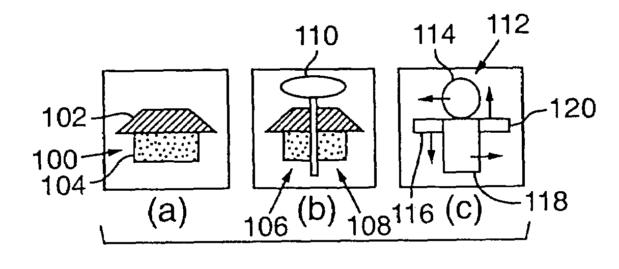
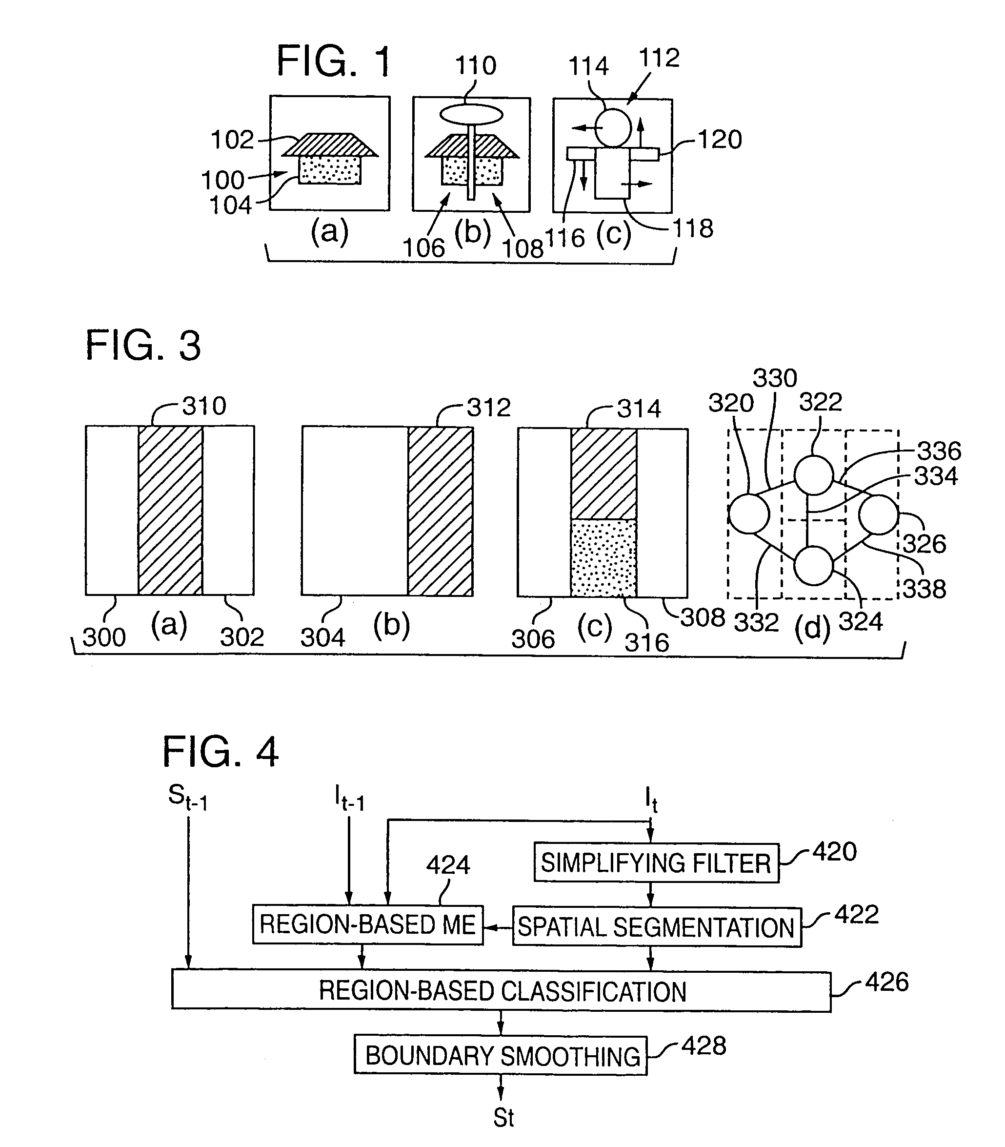
[0073]The following sections describe a specific implementation of a semantic video object tracking method in more detail. FIG. 4 is a block diagram illustrating the principal components in the implementation described below. Each of the blocks in FIG. 4 represent program modules that implement parts of the object tracking method outlined above. Depending on a variety of considerations, such as cost, performance and design complexity, each of these modules may be implemented in digital logic circuitry as well.

[0074]Using the notation defined above, the tracking method shown in FIG. 4 takes as input the segmentation result of a previous frame at time t−1 and the current vector image It. The current vector image is defined in m (m≧1) totally ordered complete lattices L1, . . . , Lm of product L (see Definition 11) on a n-dimensional set S: ∀p, pεS, It(p)={L1(p), L2(p), . . . , Lm(p)}.

[0075]Using this information, the tracking method computes a partition image for each frame in the seq...


PUM


Abstract

A semantic object tracking method tracks general semantic objects with multiple non-rigid motion, disconnected components and multiple colors throughout a vector image sequence. The method accurately tracks these general semantic objects by spatially segmenting image regions from a current frame and then classifying these regions as to which semantic object they originated from in the previous frame. To classify each region, the method perform a region based motion estimation between each spatially segmented region and the previous frame to computed the position of a predicted region in the previous frame. The method then classifies each region in the current frame as being part of a semantic object based on which semantic object in the previous frame contains the most overlapping points of the predicted region. Using this method, each region in the current image is tracked to one semantic object from the previous frame, with no gaps or overlaps. The method propagates few or no errors because it projects regions into a frame where the semantic object boundaries are previously computed rather than trying to project and adjust a boundary in a frame where the object's boundary is unknown.

Description

[0001]This is a continuation of application Ser. No. 09 / 151,368, filed Sep. 10, 1998, now U.S. Pat. No. 6,711,278.FIELD OF THE INVENTION[0002]The invention relates to analysis of video data, and more, specifically relates to a method for tracking meaningful entities called semantic objects as they move through a sequence of vector images such as a video sequence.BACKGROUND OF THE INVENTION[0003]A semantic video object represents a meaningful entity in a digital video clip, e.g., a ball, car, plane, building, cell, eye, lip, hand, head, body, etc. The term “semantic” in this context means that the viewer of the video clip attaches some semantic meaning to the object. For example, each of the objects listed above represent some real-world entity, and the viewer associates the portions of the screen corresponding to these entities with the meaningful objects that they depict. Semantic video objects can be very useful in a variety of new digital video applications including content-base...

Claims


Application Information

Patent Timeline
Patent Type & Authority Patents(United States)
IPC IPC(8): G06K9/00H04N7/18G06F7/00G06T3/00G06T7/20G06V10/24H04N7/26H04N7/32
CPCG06K9/32G06T7/0081G06T7/0097H04N19/543G06T7/2033H04N19/80G06T7/2006G06T7/11G06T7/174G06T7/215G06T7/246G06V10/24
Inventor GU, CHUANGLEE, MING-CHIEH
Owner MICROSOFT TECH LICENSING LLC
Why Eureka
Try Eureka