
Method for washing laundry in a tank-free wash path as well as wash path for carrying out the method

a technology of washing path and wash path, which is applied in the direction of other washing machines, washing machines with receptacles, textiles and papermaking, etc., can solve the problems of uncontrollable intervals, water not turning up in uniform flow, and high production costs, so as to reduce production costs, simplify the washing process, and improve the efficiency of the plant

Inactive Publication Date: 2006-08-15
SENKINGWERK
View PDF22 Cites 4 Cited by
  • Summary
  • Abstract
  • Description
  • Claims
  • Application Information

AI Technical Summary

Benefits of technology

[0007]It is, therefore, the object of the present invention to propose a washing method and to make available a wash path, in which the washing process is simplified, efficiency of the plant is improved substantially and the costs for manufacture and operation can be decreased. Simultaneously a good washing result is to be guaranteed with low water consumption and the maintenance at the machine is to be facilitated.
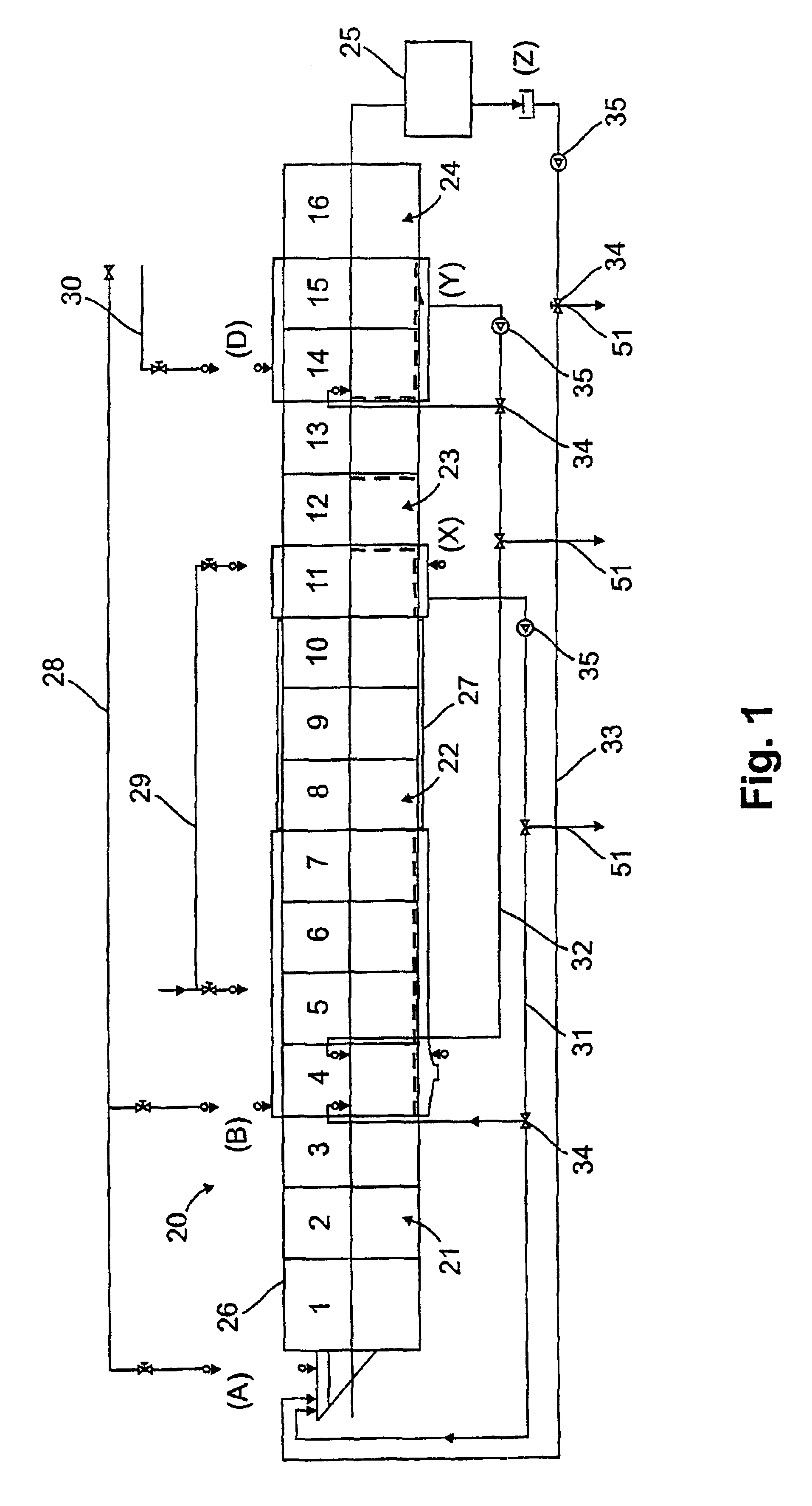
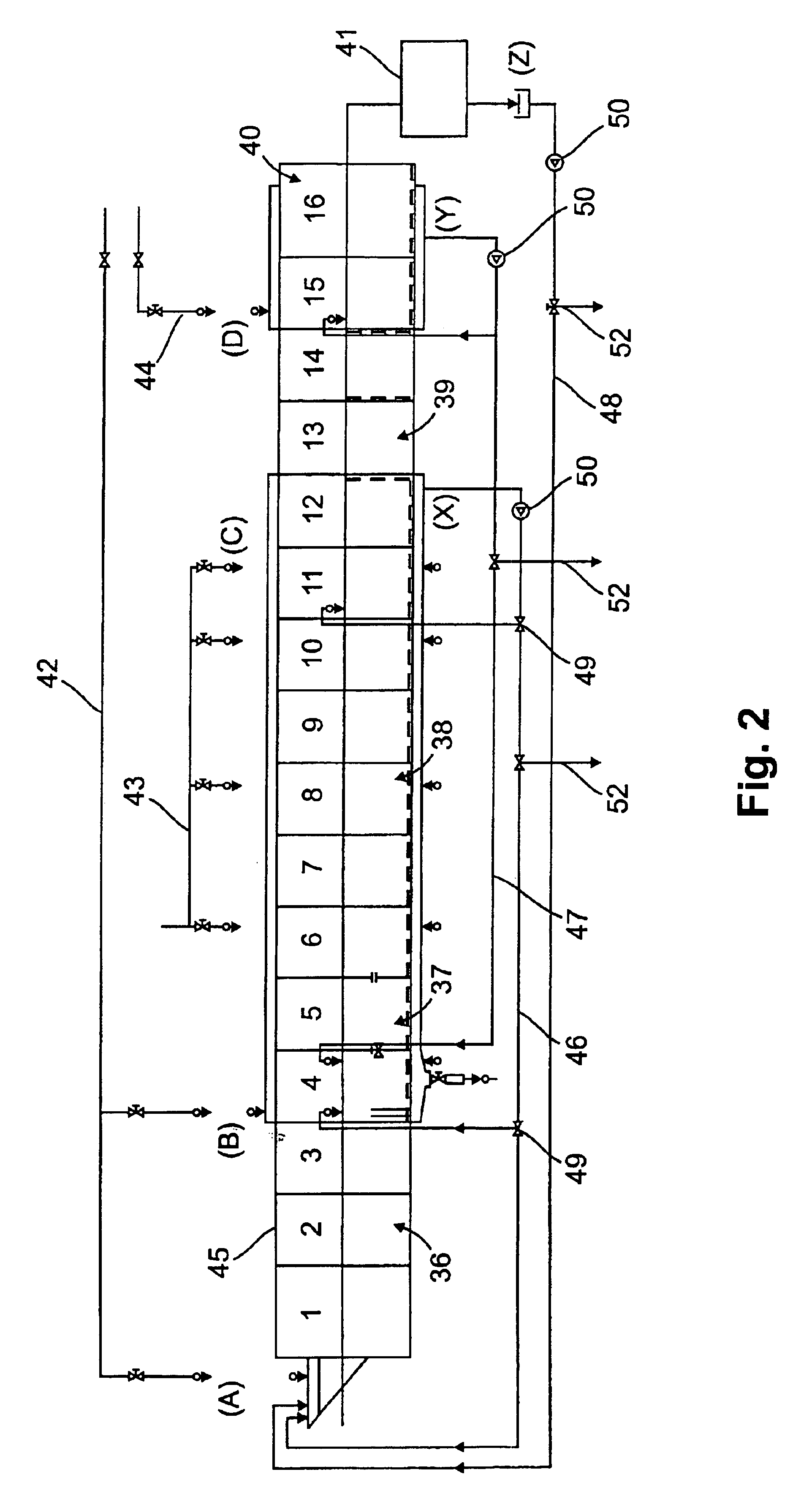
[0009]The above-described object in advantageous manner is solved in that the reusable recovered baths are not removed by overflows or outlets of the machine and intermediately are stored for then again being recharged to the machine in the required amount, but directly in the position where they occur the waste waters in exactly the required amount are pumped to the position of the wash path where they actually are needed. Buffer tanks showing the above-described drawbacks are completely omitted in advantageous manner so that the construction of a novel wash path in accordance with the invention is improved already by saving material costs but also by constructional simplification substantially, while simultaneously maintenance is made easier. In the subclaims preferred features are cited which state with respect to the method and the apparatus in which way waste water is taken from the partial zones of the wash path and again partially is supplied to preceding zones. The washing water therein variably is composed of fresh water and waste water, this being effected depending on the waste water portion so that in the respective zone a suitable amount of wash water is available. The waste water which in advantageous manner is continually taken out in exactly defined amount can be mixed with other waste water that is taken out from another zone region of the wash path as also with fresh water so that a suitable mixing ratio is adjusted. Therein, the waste water is taken out e.g. in the beginning of the rinsing zone and / or in the beginning of the aftertreatment zone and / or from a drain means located at the end of the wash path, wherein a press or a centrifuge can be used as drain means and the washing operation of pressing out the humidity from the readily washed laundry is included. Without being stored intermediately, the waste water of these zones in advantageous manner is lead to the prewashing zone. Furthermore, the waste water of the clearwashing zone can be supplied to a preceding chamber of the clearwashing zone or the waste water of the rinsing zone can be supplied to a preceding chamber of the rising zone.

Problems solved by technology

Due to the constant flow direction changes of the inner drum of said wash path as well as by different water piling-ups during passage of the laundry and the separation walls in counter flow this water, however, does not turn up in uniform flow but in gushes in intervals which cannot be controlled.
Said buffer tanks, however, include the disadvantage that they are very expensive in production, have high demand in space and have to be cleaned more frequently for hygienic reasons.
As they, however, usually are arranged below the wash paths, in most cases they are accessible with difficulty only so that cleaning of the lint seaves, removal of sand and objects is very consumptious and, therefore, expensive.

Method used


Image

  • Method for washing laundry in a tank-free wash path as well as wash path for carrying out the method
  • Method for washing laundry in a tank-free wash path as well as wash path for carrying out the method
  • Method for washing laundry in a tank-free wash path as well as wash path for carrying out the method

Examples


Embodiment Construction

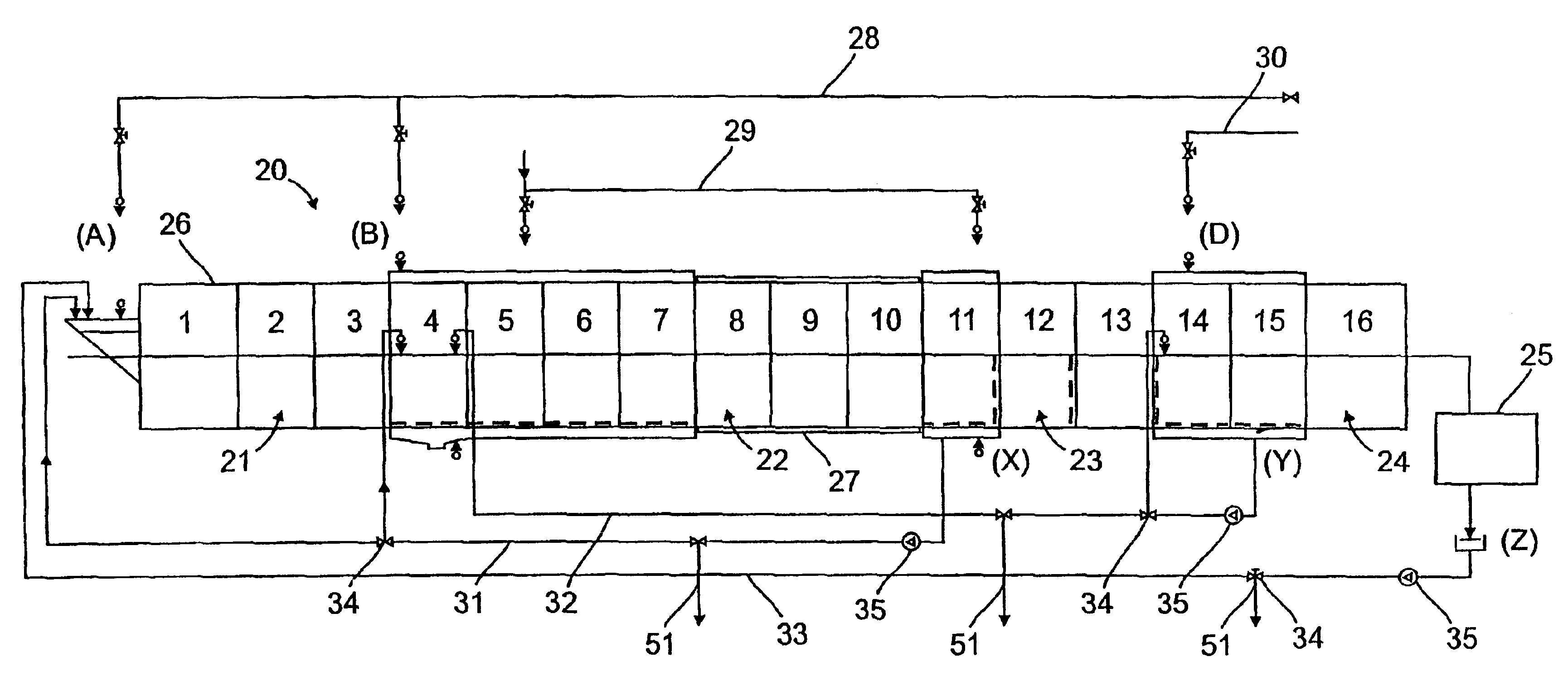
[0015]In the wash path 20 and 16 schematically shown in FIG: 2, chambers 1 to 16 are provided for which have to be correlated to the following zones:

[0016]

chambers 1 to 4prewashing zone 21chambers 5 to 10clearwashing zone 22chambers 11 to 14rinsing zonechambers 15 to 16aftertreatment zone 24

[0017]Said aftertreatment zone 24 can be followed by a drain means 25, like e.g. a press or a centrifuge.

[0018]As can be seen from FIG. 1, said chamber 1 to 16 of said wash path 20 are arranged in a drum 26 formed as double drum in the area of said chambers 4 to 7, 11 and 14 to 15. In these areas the inside wall of said drum is made punched whereas it is provided with an isolation 27 in the area of said chambers 8, 9, 10. Hereby, it is avoided that heated waters supplied from a boiler through the fresh water line 28 and / or waters, respectively, heated with addition through the vapor line 29 cools down too early in the region of the clear-washing zone.

[0019]As can be seen with reference to the sch...


PUM


Abstract

A method for washing laundry and a wash path for laundry in bath change and / or counterflow operation, in which the laundry to be washed when passing through said wash path moves through different treatment zones with chambers 1 to 16, wherein the individual baths are composed of fresh water and waste water of other baths, wherein the waste water of at least one bath without intermediate storage and directly is at least partly supplied to another bath, and wherein no waste water is intermediately stored in the water circulation during washing.

Description

[0001]This application claims priority from German Application No. 100 39 904.5. filed Aug. 18, 2000.BACKGROUND OF THE INVENTION[0002]The invention relates to a method for washing laundry, in which the laundry to be washed is moved through a wash path having subsequent chambers with different baths, wherein said laundry passes at least one of the following zones: prewashing zone, clearwashing zone, rinsing zone and after-treatment zone, and the wash water of the individual paths is composed of fresh water or fresh water and waste water of other baths. The invention further relates to a wash path for laundry in bath-change and / or counterflow operation with a washing drum with several subsequent chambers for a plurality of baths in said washing drum and a conveyor means for transferring the laundry through said washing drum as well as at least one fresh water inlet position and at least one waste water drawing-off position and inlet position for water discharge and charging.[0003]In c...

Claims


Application Information

Patent Timeline
Patent Type & Authority Patents(United States)
IPC IPC(8): D06F31/00
CPCD06F31/005Y10S68/902
Inventor STOLL, KARL-HEINZ ALEXANDER
Owner SENKINGWERK
Learn More