Waste compactor

Inactive Publication Date: 2006-08-15
IACOBUCCI
View PDF14 Cites 26 Cited by
  • Summary
  • Abstract
  • Description
  • Claims
  • Application Information

AI Technical Summary

Benefits of technology

[0011]The trolley in accordance with the present disclosure has the additional advantage of facilitating

Problems solved by technology

The operating principle of the compactors available on the market today is not particularly suited for aviation applications.
The compactors suffer from several problems, notably: the large dimensions of the waste compactor, the high electrical power required, the use of significant amounts of a pressurized oil fluid, and the use of structurally complex and costly operating and control systems in terms of construction and main

Method used


Image

  • Waste compactor
  • Waste compactor
  • Waste compactor

Examples


Example

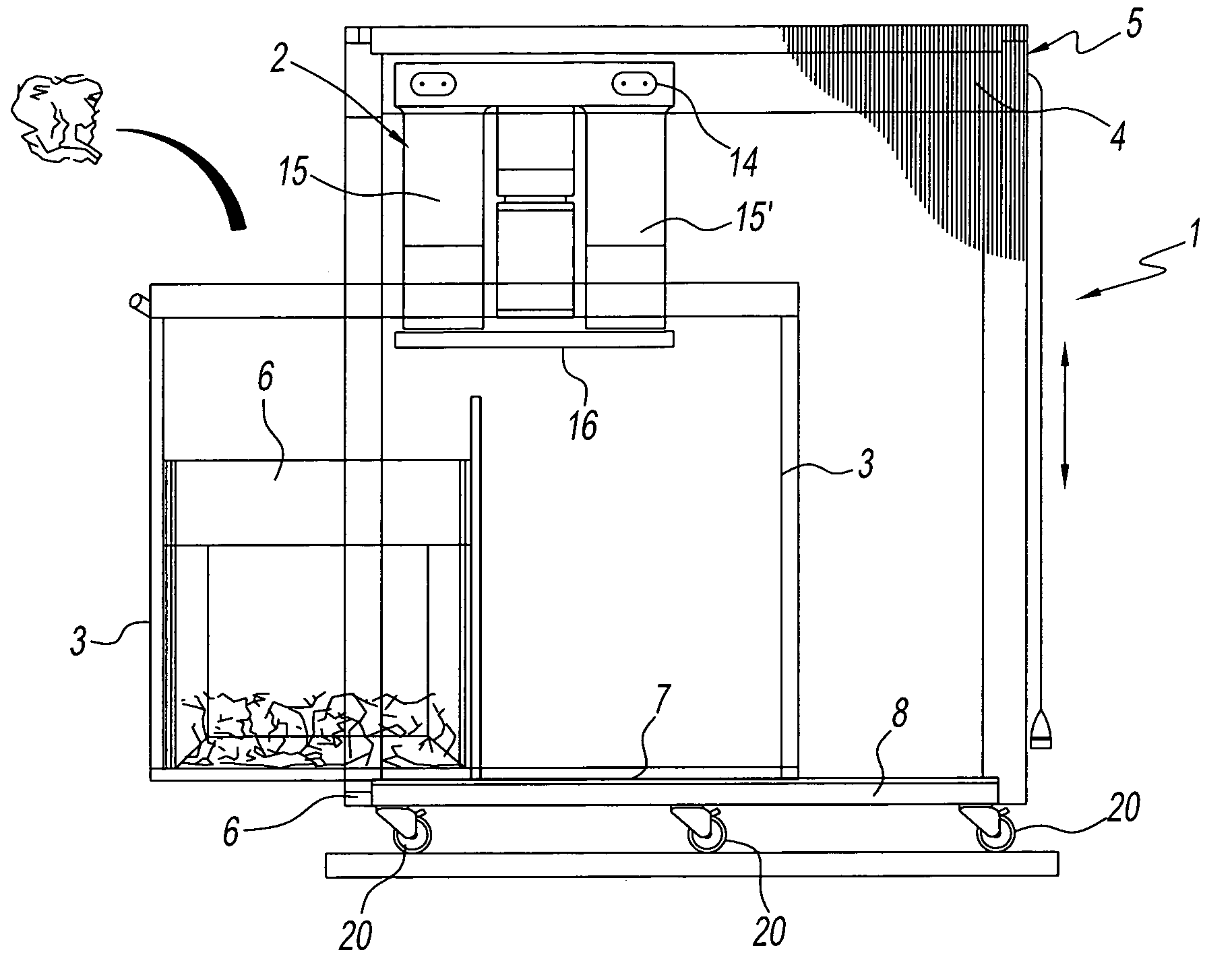
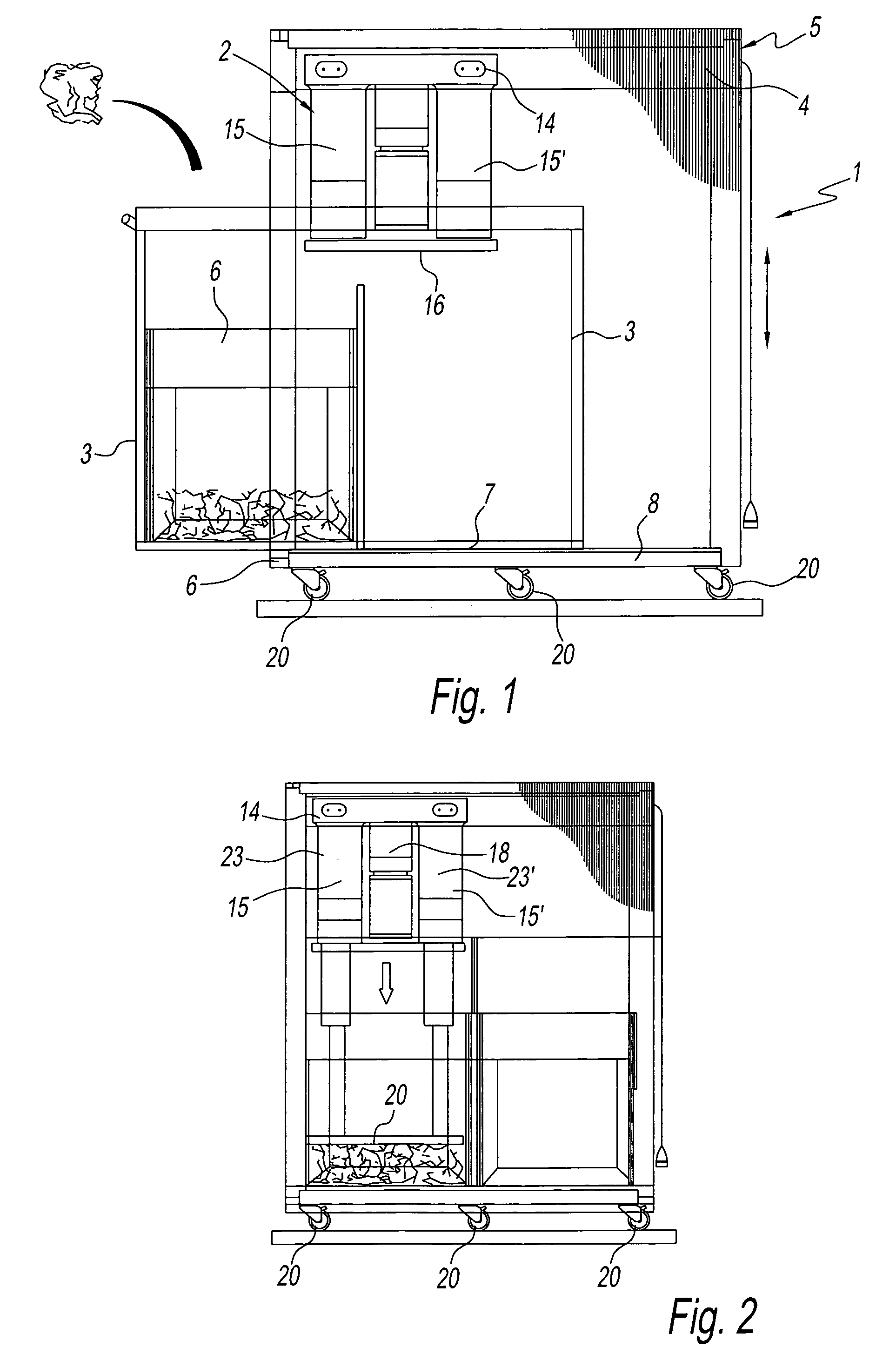
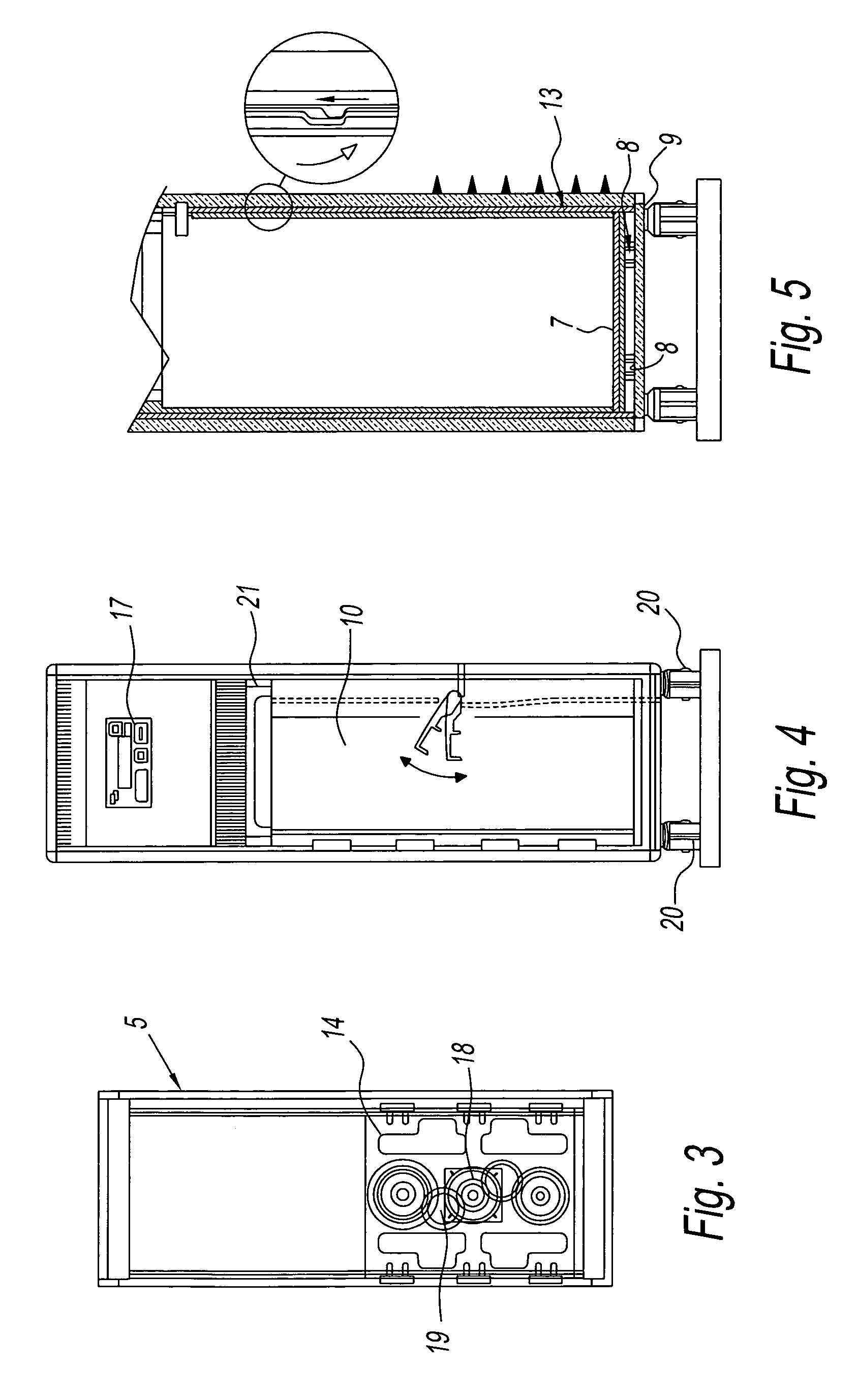
[0021]The figures show the preferred embodiments of a trolley 1 comprising a waste compactor 2 attached to a structure consisting of a moving part or drawer 3 moving from the inside to the outside of the trolley 1, a fixed part 4, and an outer casing 5. The dimensions of the trolley are typical of an aeronautical “full size trolley” or, depending on the case, “half size trolley”. In an alternative embodiment of the trolley, the fixed part 4 and the outer casing 5 comprises a single structure carrying out both functions.

[0022]The waste compactor 2 comprises an electric motor 18, preferably a motor reducer, that generates rotary motion and is connected to mechanisms comprising a reducing unit 19 and two telescopic screws 15, 15′. The telescopic screws drive the horizontal, metal, compaction plate 16 by means of vertical, translational motion. For improved mechanical stability, the system should preferably consist of two paired screws 23, 23′ driven by a single electric motor. Preferab...


PUM


Abstract

A trolley suitable for aircraft or use in all space constraint situations comprising a waste compactor comprising a metal horizontal plate driven by an electric motor reducer that, by a mechanical reducer, drives two telescopic screws responsible for pushing the horizontal plate onto the waste, compacting it.

Description

TECHNICAL FIELD[0001]This invention relates to a waste compactor. More specifically, it relates to a waste compactor for compacting trash produced on civil aviation aircrafts during flights and a trolley for housing said waste compactor.[0002]The waste compactor can handle items such as plastic or paper plates and cups, plastic cutlery, aluminium drink cans, aluminium food containers, Tetrapak-type cartons, paper napkins, etc.BACKGROUND ART[0003]Waste compactors, like all the other accessory equipment used onboard aircrafts, must comply with specific, strict requirements provided for by aeronautical regulations. Specifically, the dimensions and structural characteristics of all civil aircraft accessories must be able to support the loads specified in the applicable regulations in force; furthermore, the accessories must be suitable for being housed and stored in safety during travel in specific aeroplane compartments. Finally, the accessories must be as light as possible.[0004]Reduc...

Claims


Application Information

Patent Timeline
IPC IPC(8): B30B1/18B30B9/30
CPCB30B9/3064B30B9/3092B64D11/0007
Inventor IACOBUCCI, EMILIO
Owner IACOBUCCI
Why Eureka
Try Eureka