Chain tensioner

a chain tensioner and chain technology, applied in the direction of belts/chains/gearings, machines/engines, machines/engines, etc., can solve the problems of reducing damping performance, difficult to machine latching grooves, and affecting the operation of chain tensioners, so as to facilitate the disassembly and maintenance of the chain tensioner, the effect of enhancing operational stability

Inactive Publication Date: 2006-11-30
NTN CORP
View PDF12 Cites 19 Cited by
  • Summary
  • Abstract
  • Description
  • Claims
  • Application Information

AI Technical Summary

Benefits of technology

[0039] A set wall that is mated with the second stopper through the resister ring is formed on the outer periphery of the plunger before the foremost latching groove. Then the plunger can be held in the state (initial state) in which the plunger sinks deep in the housing and thus it becomes easy to handle during transportation. This initial set can be easily released by radially expanding the resister ring so that an inner diameter of the resister ring becomes larger than an outer diameter of the set wall.
[0040] A safety wall that is mated with the second stopper through the resister ring is formed on the outer periphery of the plunger after the rearmost latching groove. Then it is ensured that the plunger does not come off the housing when pushed by the return spring. In this case, the plunger can be removed from the housing by radially expanding the resister ring so that the outer diameter of the resister ring becomes larger than the outer diameter of the safe wall. Then it becomes easy to disassemble...

Problems solved by technology

In this chain tensioner, when the chain is held tense depending on the stopping posture during a standstill of the engine, the plunger pushed by the chain may sink considerably deep.
Such an insufficient oil supply to the hydraulic damper chamber may cause air intrusion into the hydraulic damper chamber and result in unusual noises, degrading the damping performance.
However, since the latching groove is formed on the inner peripheral surface of the cylindrical casing, it is difficult to machine the latching groove with high accuracy and the manufacturing cost becomes high.
Therefore, a complex and high precision groove machining is required for the piston and the casing so that the absorbing piston is not locked by the stopper ring when the absorbing piston is inserted in the casing during assembly.
(5) It is difficult to separate the piston from the casing because the resister ring cannot be manipulated from the outside.
Thus ma...

Method used


Image

  • Chain tensioner
  • Chain tensioner
  • Chain tensioner

Examples


Embodiment Construction

[0056] Now, preferred embodiments of the present invention will be described below based on FIGS. 1-12.

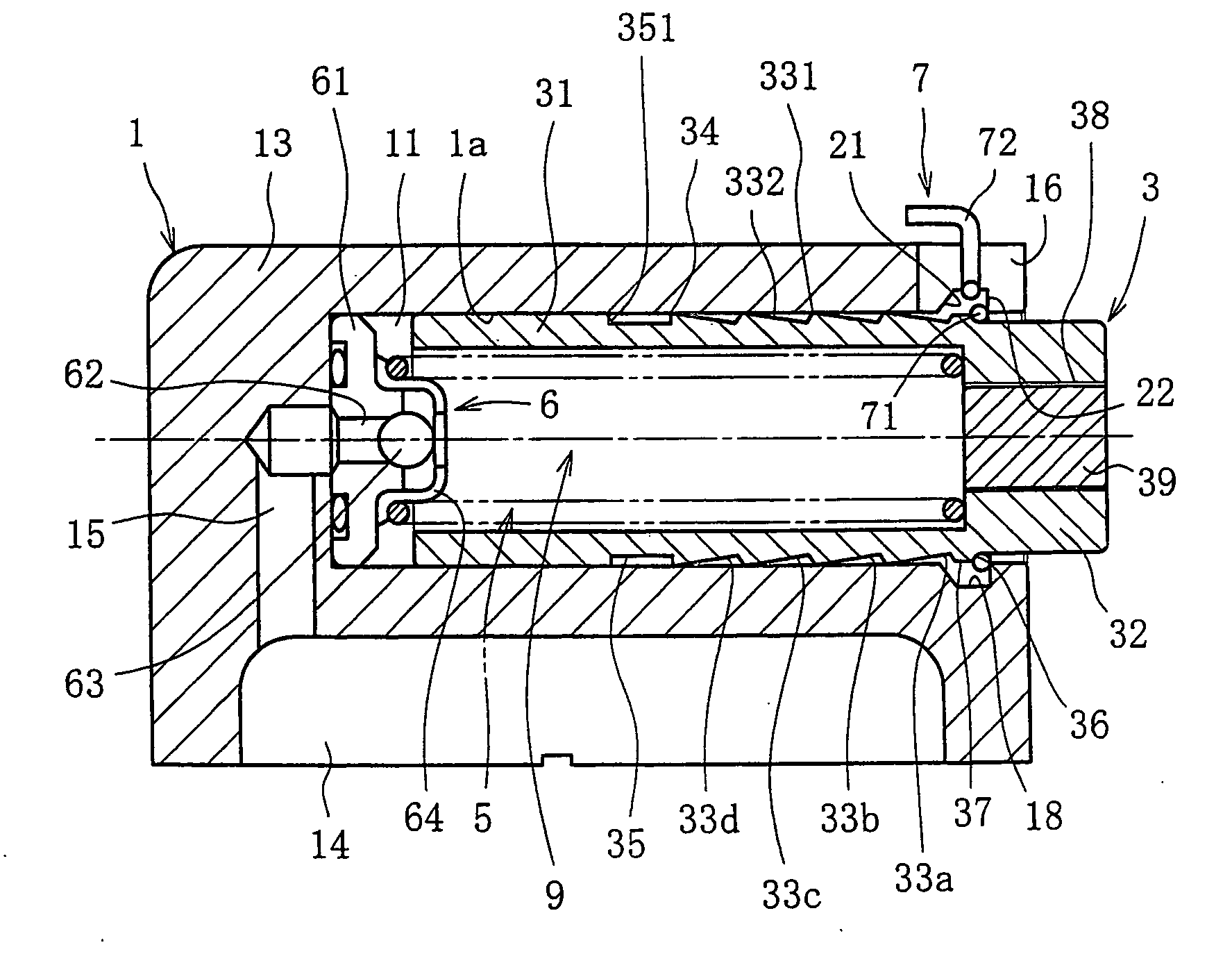
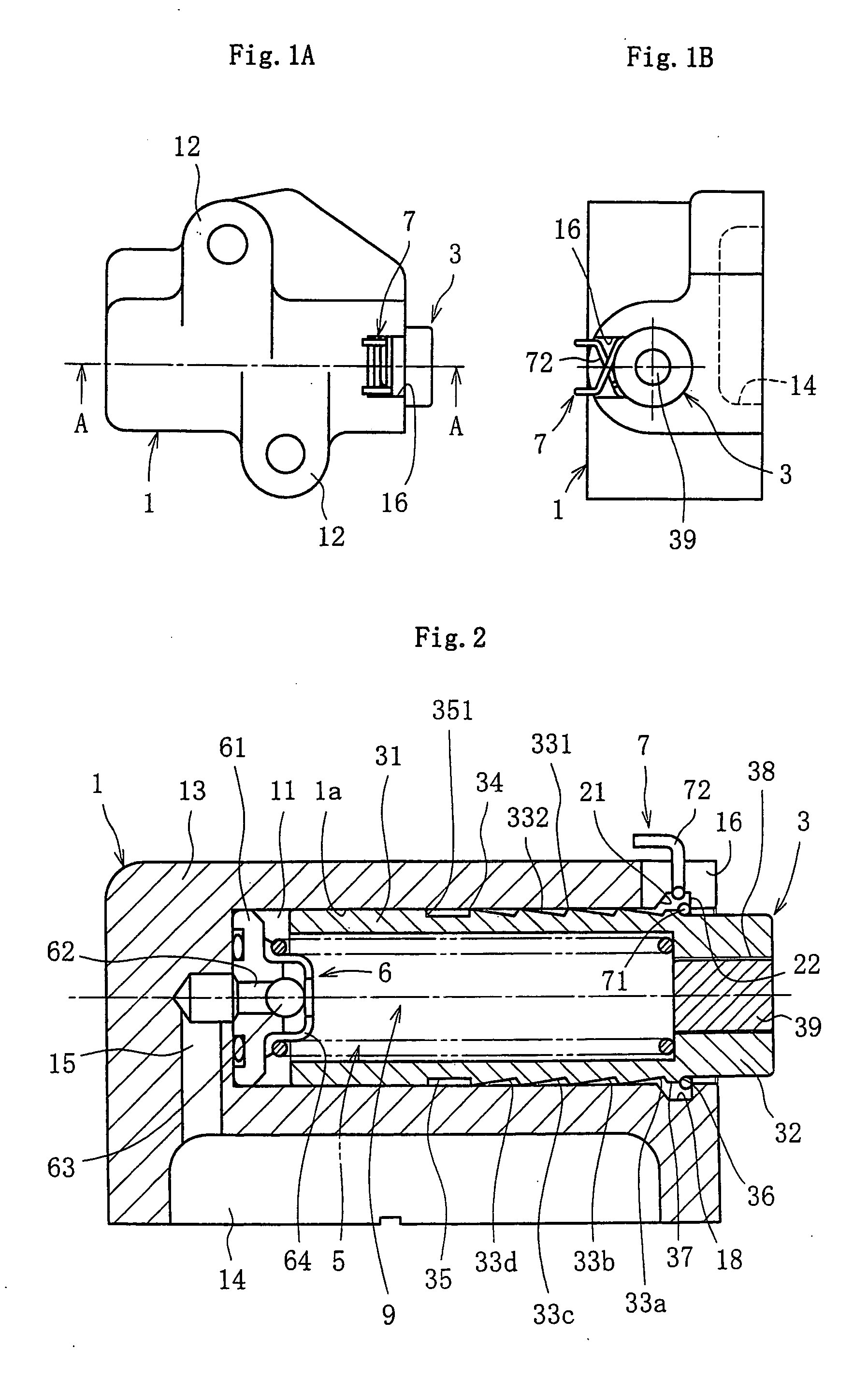
[0057] Referring now to FIG. 1 and FIG. 2, a chain tensioner according to the present invention is composed of the major components such as a housing 1, a plunger 3 installed in the inner periphery of the housing 1, a return spring 5, a check valve 6 and a resister ring 7 fit on the outer periphery of the plunger 3. Note that in the explanation that follows, the direction the plunger 3 projects is called “front” (right-hand side in FIG. 1A, FIG. 2, FIG. 3, FIGS. 7-9), while the direction the plunger 3 retracts is called “back” (left-hind side in the same figures).

[0058] A hollow cylinder unit 11 for incorporating the plunger 3 is formed in the tubular housing 1 that has a bottom. Mounting portions 12 for mounting on an engine block are formed on both sides of the cylinder unit 11 (see FIG. 1A). An oil supply passage 15 is formed in the bottom 13 of the housing 1 so as to guide op...


PUM


Abstract

This invention provides a chain tensioner that is compact, excellent in operation, easy to maintain and handle and low in manufacturing cost. This chain tensioner has a tubular housing 1 having a bottom, a plunger 3 installed in the inner periphery 1a of the housing so as to smoothly slide inside the housing, a return spring 5 providing the plunger 3 with a force pushing outward, a plurality of latching grooves 33a-33d formed on the outer periphery of the plunger 3, a resister ring 7 capable of locking in the latching grooves, and a check valve 6 that is mounted on the bottom of the housing inner periphery 1a, provides the housing inner periphery 1a with operating oil and prevents its reverse flow. The range of backward movement of the plunger 3 is limited by mating the resister ring 7 locked in the latching grooves 33a-33d with a first stopper 21 formed on the housing inner periphery 1a.

Description

CROSS REFERENCE TO RELATED APPLICATION [0001] This is a Continuation Application, which claims the benefit of pending U.S. patent application Ser. No. 10 / 111,631, filed Dec. 10, 2002. The disclosure of the prior application is hereby incorporated herein in its entirety by reference.TECHNICAL FIELD [0002] The present invention relates to a chain tensioner that keeps the tension of chains, for example, a chain for driving a camshaft, constant. BACKGROUND ART [0003] In general, chain drive systems, for example, a chain drive system that transmits rotation force of a crankshaft to a camshaft in a engine of a car, has a chain tensioner provided on its slack side to keep the chain tension constant. [0004] As a conventional chain tensioner, such a mechanism is known that has a spring and a plunger incorporated in a housing and the spring provides the plunger with a repulsive force toward the outside of the housing. In the chain tensioner of this type, the plunger pushed by the spring provi...

Claims


Application Information

Patent Timeline
IPC IPC(8): F16H7/08F16H7/22F02B67/06
CPCF16H7/0836F16H2007/0806F16H2007/0812F16H2007/0878F16H2007/0855F16H2007/0859F16H2007/0853
Inventor YAMAMOTO, KENMAENO, EIJI
Owner NTN CORP
Why Eureka
Try Eureka